
Chapter 6 - Energy Sustainability
Part 3 - Electricity: Transmission, Distribution and Economics
Delivering Electricity to End Users
B. Transformer Basics and Losses
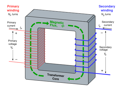
Transformers appear in critical places in a power schematic. They STEP UP the voltage after generation for efficient transmission and then also STEP DOWN voltage for distribution to end users. Transformers comprise a majority of tramsmission and distribution losses in many electrical power delivery systems. AC voltage increases automatically with the number of turnings or windings on the primary and secondary circuits. (The transformer in the image is a STEP DOWN transformer because it has lower voltage on the secondary terminals). Losses occur in one of two ways: No-load or Core losses are caused by the magnetizing current needed to energize the core of the transformer, and do not vary according to the loading on the transformer; they are constant, 365 days of the year, 24 hours of the day. Load or Winding losses vary according to the loading on the transformer. They include heat losses and eddy currents in the primary and secondary conductors of the transformer. Heat loss is current, I, squared and multiplied by resistance, R (heat loss = I^2R). Heat losses in the winding materials contribute the largest part of heat loss, and are due mostly to the resistance within the conducting material to the flow of electrons. In a typical 75kV transformer loss profile, the losses appear to be about 4% of the delivered power between 50 and 100% loading.
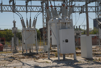 Transformers make it easy to change voltages. Transformers are generally located in substations near the generating plant. A step-up transformer performs similarly to a pump building up pressure in a hose, raising the voltage to levels anywhere from 69,000 to 750,000 volts, depending on the distance to be travelled by the current and the amount desired. The highest voltage AC transmission line is in Kazakhstan, which carries 1,150kV. A step-down transformer is located in a distribution substation, and reduces the voltage in order for it to be carried on smaller cables or distribution lines. Smaller transformers on poles, pads or underground further reduce the voltage to 120 or 240 volts for residential use. Industrial customers using large amounts of power usually require higher service voltages.
Part 3 - Electricity: Transmission, Distribution and Economics
Delivering Electricity to End Users
A. Basic Structure of Electric Power System
B. Transformer Basics and Losses
C. Transmission Lines and Grid Operations (NEXT)
D. Environmental, Health and Safety Issues – T&D
E. System Losses Weigh Heavily on Electricity Systems in Developing Countries
F. A Revolution in the Electricity Sector?
G. Small-Scale Power: Distributed Generation
Summary: Smart-Grid: A Game-Changing Technology
Electricity Markets and the Future of Electricity
(Adapted from the Energy Resources lecture materials of Jane Woodward, Consulting Associate Professor of Civil and Environmental Engineering and Karl Knapp, Lecturer of Civil and Environmental Engineering at Stanford University by Cheryl Chadwick/Gregory Möller)
(Image credits: Power Transformer, Inc.; Linder6580)
