Introduction
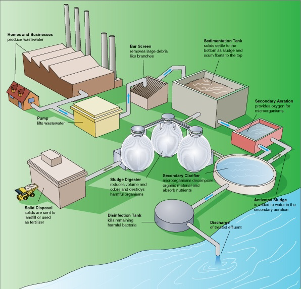
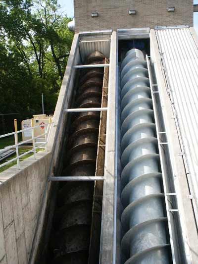
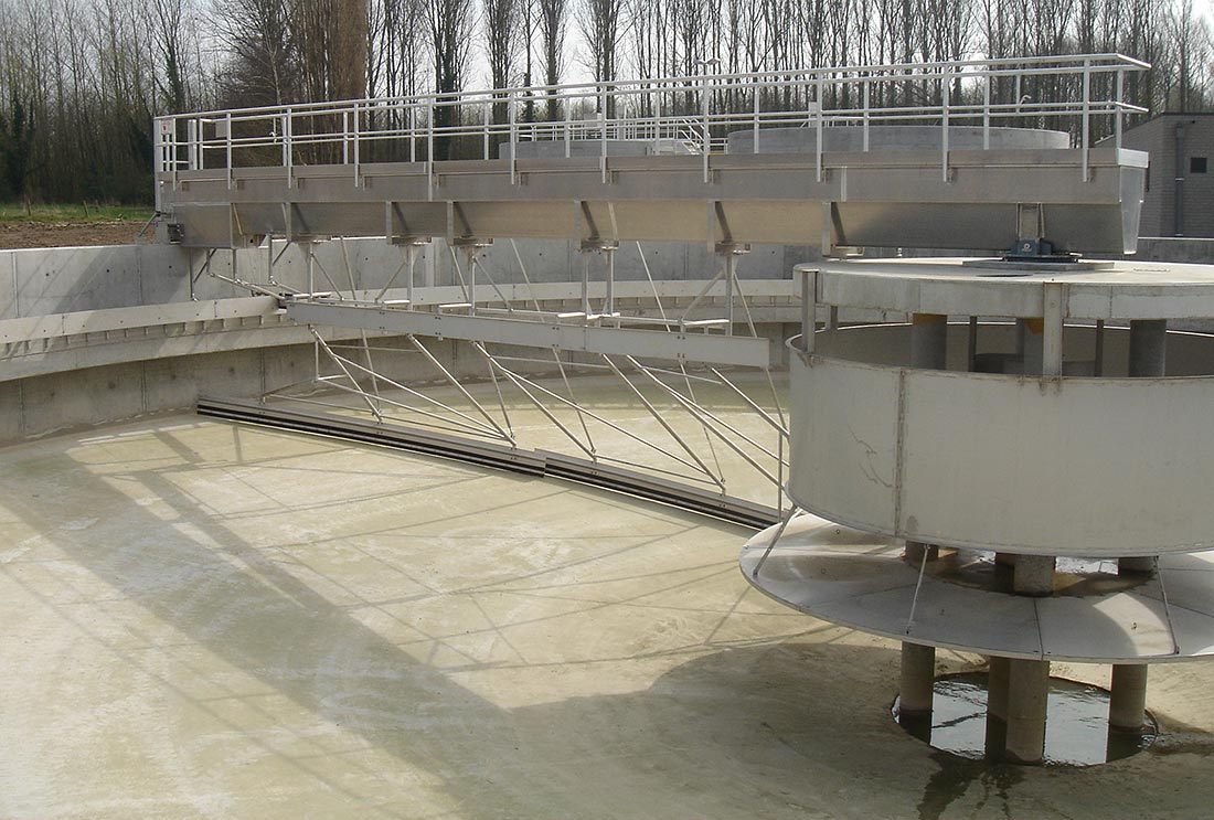
Left: Conventional Wastewater Treatment Plant. Middle: Screw pumps Photo: Flake Bruins-ma. Right: Photo: Annabel, license CC-BY-SA-3.0
In urban and suburban areas, there is a lot of wastewater to treat. Communities typically construct a sewer system that collects wastewater and drains it to an industrial wastewater treatment facility.
Ideally, the water in the sewer pipe system flows by gravity. Pipes from each building connect to a sewer mainline that runs under the street. The sewer mainline might be 3 to 5 feet in diameter. Periodically, and where pipes intersect, a vertical pipe will run from the mainline to the surface, where it is covered by a manhole cover. Manholes allow access to the mainline for maintenance purposes.
The sewer mains flow into progressively larger pipes until they reach the wastewater treatment plant. In order to help gravity do its job, the wastewater treatment plant is usually located at the lowest elevation in the city, and sewer mains will often follow stream beds to the plant.
Normally, the topography of the land will not cooperate completely, and gravity can not do all the work. In these cases, the sewer system will include a grinder-pump (above middle) or a lift station to move the wastewater over a hill.
Enlarge the first image above. Note the five step process to achieve secondary quality effluent. The sedimentation tank (primary clarifier) simply allows solids to settle to the bottom where they are collected as sludge. This is the end of the primary treatment phase. The next tank is called the secondary aeration tank in the diagram above. Notice that activated sludge is delivered to this tank. This sludge is biomass teeming with bacteria and protozoa that consume organic material and convert ammonia to nitrate. The next tank is the secondary clarifier. Here dead bacteria and other solids settle to the bottom of the tank and are removed to the sludge treatment area. In the process diagram above which tank includes aeration of the water?
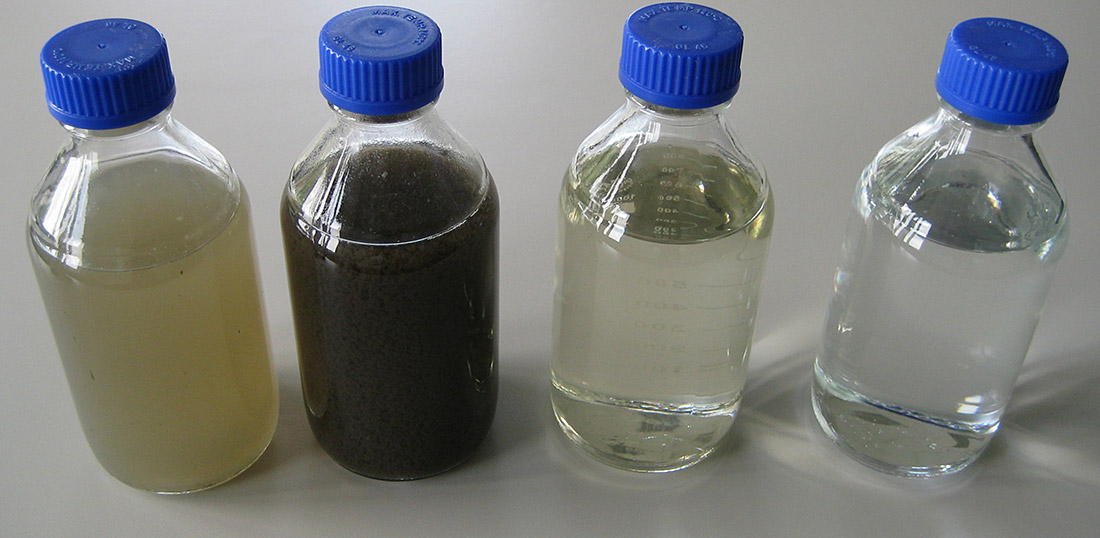
Raw domestic wastewater typically consists of approximately 99.9 percent water (by weight) and 0.03 percent suspended solids. Enlarge the image, above right, to see the quality of the water at each step of the treatment process. The first bottle shows the raw sewage after screening and settling in the primary sedimentation tank. The second bottle shows the water in the secondary aeration tank after the activated sludge has been added (to improve bacterial consumption of organic material). The third bottles contains water ready to be discharged from the waste water treatment plant and can be compared to the last bottle containing potable drinking water.
Primary Treatment
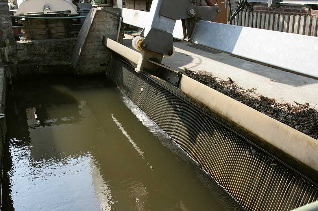
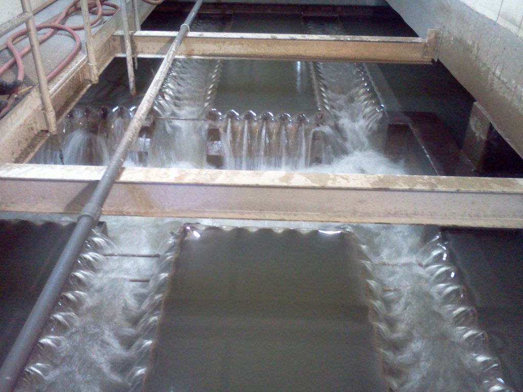
Left: Bar screen. Photo: Frank Vincentz, license CC-BY-SA-3.0. Middle: Sedimentation Tank. Photo: MADe license CC-BY-3.0. Right: This is the end of primary treatment. The water is being aerated before transfer to the secondary aeration tank. Photo:WESA, license CC-BY-SA-2.0
Once the water reaches the wastewater treatment plant, it goes through two or three stages of treatment, depending on the sophistication of the plant. The first stage, known as primary treatment, allows the solids to settle out of the water and the scum (containing oil and grease) to rise. The solids (sludge) are collected for further treatment and disposal in a landfill or an incinerator. Primary treatment is very simple -- it involves a bar screen followed by a set of tanks or ponds that let the water sit so that the solids can settle out. Primary treatment might remove half of the solids, organic materials and bacteria from the water.
Secondary Clarifiers
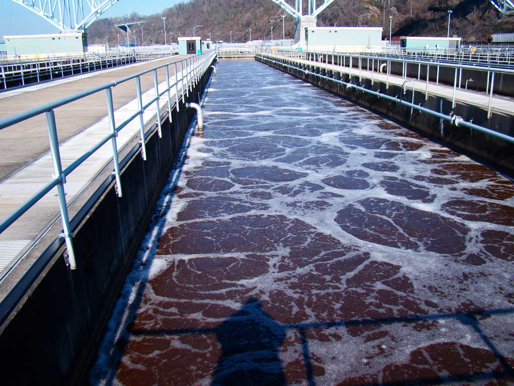

Left: Aeration tank with activated sludge. Photo: WESA, license CC-BY-SA-2.0 Right: Pumps at a waste water treatment plant Photo: Maciej-Pres, license CC-BY-SA-3.0
The second stage, known as secondary treatment, removes organic materials and nutrients. This is done with the help of bacteria -- the water flows into large, aerated tanks where bacteria consume organic material, pathogenic bacteria and other substances. Then the wastewater flows into settling tanks where the bacteria settle out. Secondary treatment might remove 90% of all solids and organic materials from the wastewater.
Conventional treatment plants treat huge quantities of water within a small land area. To do this requires industrial pumps and aerators. The consume a great deal of energy as well as operations and maintenance costs. Chemicals to control and enhance the process for high efficiency is another input. This method of wastewater treatment is also a centralized model that limits reuse of the wastewater.
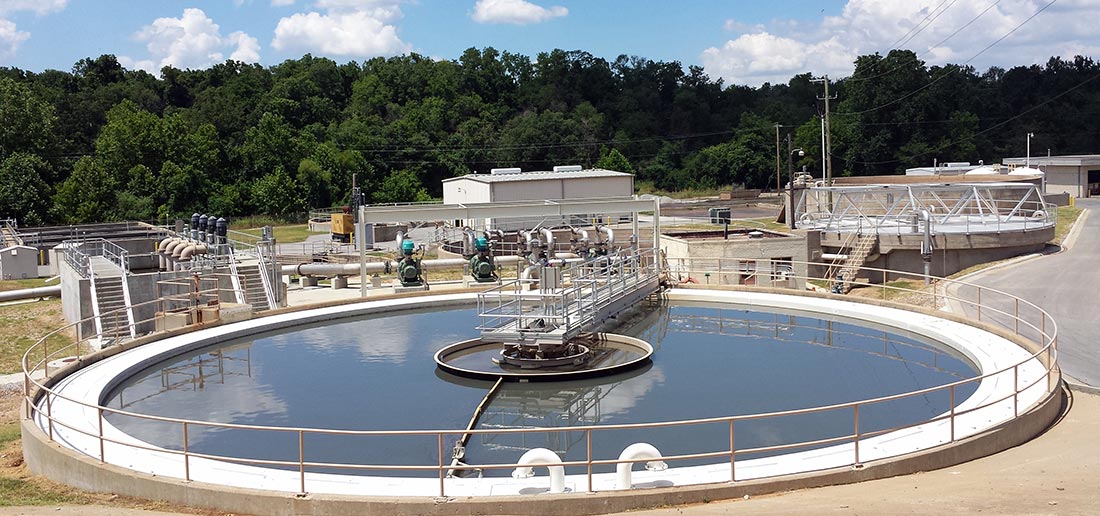
Left: Secondary Clarifier at Siloam Springs W W T P . Photo Brandon Rush, license CC-BY-SA-3.0. Right: Chlorination Tank. Photo: Flake Bruins-ma.
The third stage, known as tertiary treatment, varies depending on the community and the composition of the wastewater. Typically, the third stage will use chemicals to remove phosphorous and nitrogen from the water, but may also include filter beds and other types of treatment. Chlorine added to the water kills any remaining bacteria, and the water is discharged.
Measuring the Effectiveness of a Treatment Plant
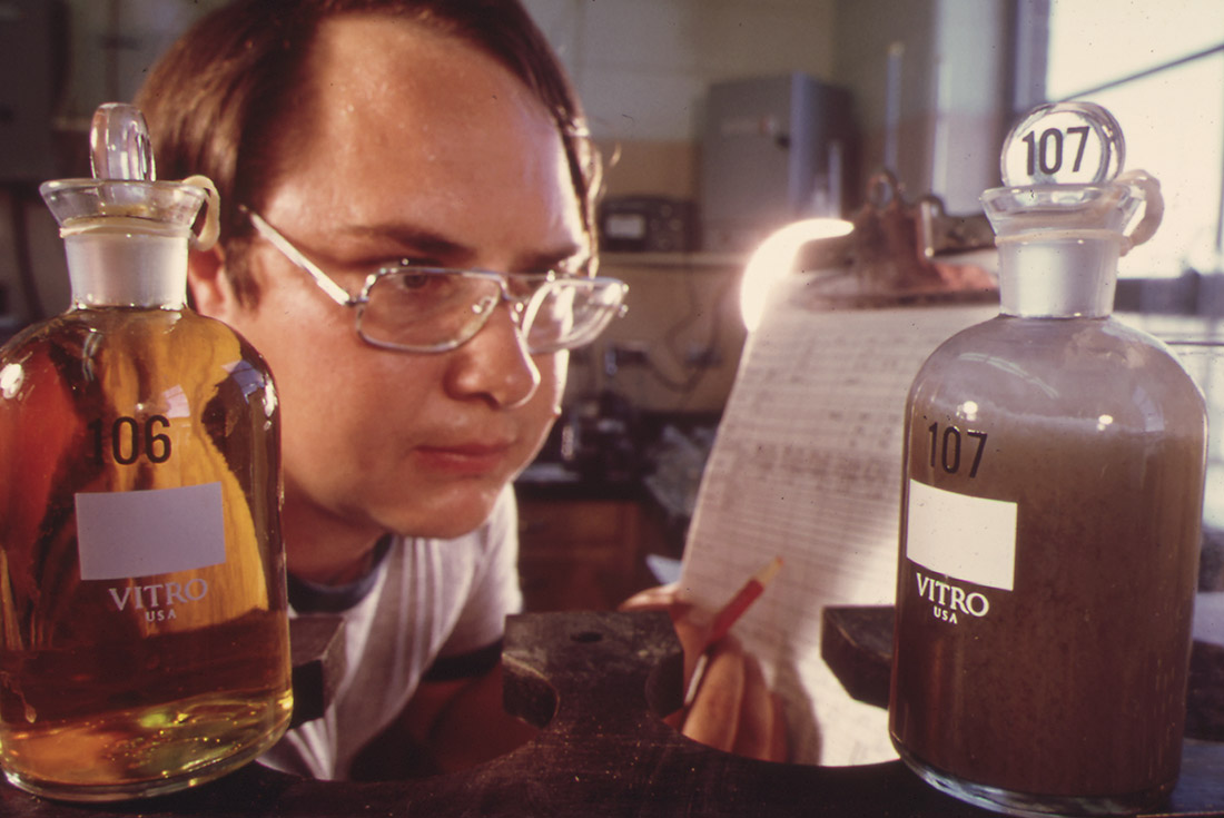
BOD test at a wastewater treatment plant. Photo: Bill Gillette, public domain.
Raw Sewage Characteristics
Component |
Concentration Range |
Typical Concentration |
Total Suspended Solids |
155 – 330 mg/L |
250 mg/L |
Biological Oxygen Demand |
155 – 286 mg/L |
250 mg/L |
pH |
6 -9 s.u. |
6.5 s.u. |
Total Coliform Bacteria |
108– 1010 CFU/100mL |
109 CFU/100mL |
Fecal Coliform Bacteria |
106 – 108 CFU/100mL |
107 CFU/100mL |
Ammonium-Nitrogen, NH4-N |
4 - 13 mg/L |
10 mg/L |
Nitrate-Nitrogen, NO3-N |
Less than 1 mg/L |
Less than 1 mg/L |
Total Nitrogen |
26 – 75 mg/L |
60 mg/L |
Total Phosphorus |
6 - 12 mg/L |
10 mg/L |
(1) Source: U.S. EPA Onsite Wastewater Treatment Design Manual
mg/L = milligrams per liter, s.u. = standard units, CFU/100 mL = Colony-Forming Units per 100 milliliters
• pH - This is the measure of the water's acidity once it leaves the plant. Ideally, the water's pH would match the pH of the river or lake that receives the plant's output. Standards generally require pH between 6.5 and 9.
• BOD (biological oxygen demand) - BOD is a measure of how much oxygen in the water will be required to finish digesting the organic material left in the effluent. Ideally, the BOD would be zero. The EPA standard for secondary effluent is 30 mg/l.
• Dissolved Oxygen - This is the amount of oxygen in the water as it leaves the plant. If the water contains no oxygen, it will kill any aquatic life that comes into contact with it. Dissolved oxygen should be as high as possible and needs to cover the BOD. If dissolved oxygen concentrations drop below 5 mg/L (or parts per million), fish will be unable to live for very long. Trout require at least 8 mg/l of DO and salmon need around 11 mg/L.
• Total Suspended Solids - This is the measure of the solids remaining in the water after treatment. Ideally, suspended solids would be zero. The standard for TSS is not more than 30 mg/L.
• Total Phosphorous and Nitrogen - This is the measure of the nutrients remaining in the water. Levels over 30 mg/L of nitrate can inhibit growth, impair the immune system and cause stress in some aquatic species. The EPA has established a maximum contaminant level of 10 mg/L for nitrate in drinking water, but the maximum for babies is 1 mg/L . Excessive nitrate can result in restriction of oxygen transport in the bloodstream.
Phosphorous is a nutrient that in excess causes algae blooms. In some places levels of 1 mg/L results in sophistication of lakes. Effluent limits usually range from 0.1-2 mg/L, with many established at 1.0 mg/L. Effluent from treatment plants can achieve 0.1 to 0.05 mg/L with new processes and control of initial levels (by banning the sale of detergents and soaps containing phosphorous).
• Chlorine - The chlorine used to kill harmful bacteria needs to be removed so it does not kill beneficial bacteria in the environment. Ideally, chlorine should not be detectable.
• Coliform bacteria Count - This is an indirect measure of fecal bacteria remaining in the water. Fecal coliform bacteria are much more common than pathogens that are a threat to human health. The amount of fecal coliform bacteria correlates to the amount of pathogens. Ideally, this number would be zero. Note that water in the environment is not totally free of fecal bacteria -- birds and other wildlife do introduce some.
The current EPA recommendation for body-contact recreation (swimming and wading) is fewer than 100 colonies/100 mL. For fishing and boating the standard is fewer than 1,000 colonies/100 mL. A test for E. coli bacteria is also used to estimate the amount of pathogenic bacteria in water. The primary recreational contact (swimming) standard for E. coli is 126 colonies per 100 mL
Any community produces a huge quantity of wastewater. Discharge levels ranging from 10 million to 100 million gallons per day are common for wastewater treatment plants. So quality standards are important protections.
Residential Wastewater Treatment
Septic Tank and Field Systems
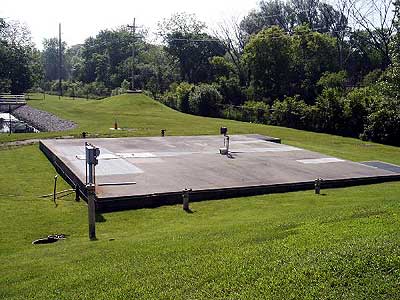
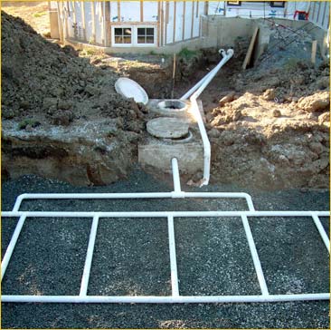
In rural areas people install their own, private sewage treatment plants. These are called septic tanks and leach fields. Wastewater comes into the septic tank from the sewer pipes in the house, as shown here.
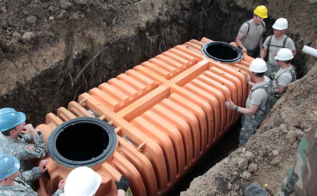
Left: Community Septic System. Right: Installation of a septic tank.
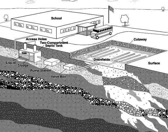
A septic tank is a concrete, steel or plastic tank that is buried. The tank might hold 1,000 to 20,000 gallons of water. Wastewater flows into the tank at one end and leaves the tank at the other. Enlarge the image at, above left, to see the configuration of a typical system for a school. The tank looks something like the one below in cross-section.
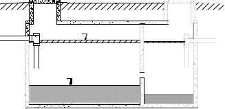
Single Chamber Septic Tank - Section
Two Chamber Septic Tank - Section. Image: Gross.
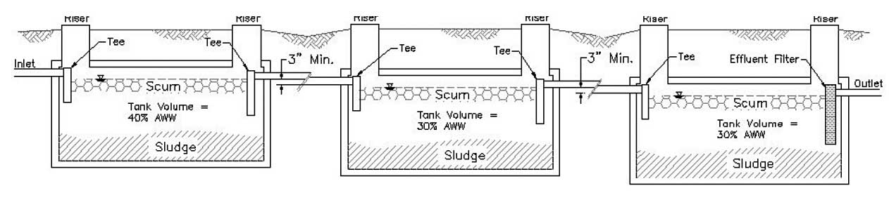
Three septic tanks in series for a community system for 100-250 people. Note that there is a 40% - 30% - 30% water capacity in the tree tanks. Image: Iowa Department of Natural Resources.
In the drawings above, you can see three layers inside the septic tanks. Grease, oil and anything that floats rises to the top and forms a scum layer. Anything heavier than water sinks to form the sludge layer. In the middle is a relatively clear water layer. This body of water contains bacteria and nutrients like nitrogen and phosphorous that act as fertilizers, but it is largely free of large solids.
Septic tanks may contain one or two (or more) compartments, with at least two recommended, particularly for large systems (US EPA, 1980a). There are highly efficient septic tanks available. These have two or more compartments and an effluent filter. The compartments ensure that settleable solids remain in the tank and minimize the effect of peak flows. The first compartment in a two-compartment tank typically accounts for two-thirds of the available volume and retains most of the solids, while the remaining tank volume provides clarification of the wastewater (US EPA, 1997b). Effluent filters installed at the tank outlet reduce the concentration of total suspended solids. Effluent filter inserts produce effluent with an average Total Suspended Solids (TSS) concentration less than 30 ppm (almost 2.5 times less than a non-screened system) (Orenco, 1997).
A septic tank naturally produces gases (caused by bacteria breaking down the organic material in the wastewater), and these gases don't smell good. Sinks, therefore, have loops of pipe called P-traps that hold water in the lower loop and block the gases from flowing back into the house. The gases flow up a vent pipe instead.
If twenty persons or more are connected to a common septic system (about 2,000 gallons per day), then the system is subject to federal regulation.
States generally characterize large systems using flow definitions that range from 2,000 to 20,000 gallons-per-day (gpd). Regulation is highly variable across states. Some states have stringent requirements for large systems. For example, Massachusetts and Minnesota both use 10,000 gpd as the cutoff for large systems and have strict requirements for siting, construction, and operation.
Typical effluent concentrations from septic tanks equipped with effluent filters range from 100 to 140 mg/L for BOD, 20 to 55 mg/L for TSS, and 10 to 20 mg/L for oil and grease (Crites and Tchobanoglous, 1998; Stuth, 2004). Notice that the TSS value is lower than in the table below, due to the filter.
Component |
Concentration Range |
Typical Concentration |
TSS |
36 - 85 mg/L |
60 mg/L |
BOD |
118 - 189 mg/L |
120 mg/L |
pH |
6.4 – 7.8 s.u. |
6.5 s.u. |
Fecal Coliform Bacteria |
106 – 107 CFU/100mL |
106 CFU/100mL |
Ammonium-Nitrogen, NH4-N |
30 – 50 mg/L |
40 mg/L |
Nitrate-Nitrogen, NO3-N |
0 – 10 mg/L |
0 mg/L |
Total Nitrogen |
29.5 – 63.4 mg/L |
60 mg/L |
Total Phosphorus |
8.1 – 8.2 mg/L |
8.1 mg/L |
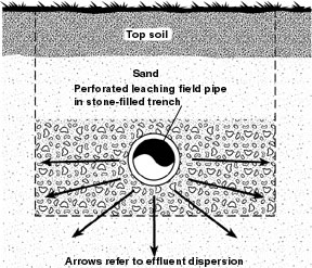
Drain field Diagram. Enlarge to see the system components, Photo: Redstarpublications, license CC-BY-SA-3.0
As new water enters a septic tank, it displaces the water that's already there. This water flows out of the septic tank and into a drain field. A drain field is made of perforated pipes buried in trenches filled with gravel. This diagram shows a plan view of a house, septic tank, distribution box and drain field. The septic tank is at B. C is a concrete splitter box that divides the flow among three pipes, D.
The septic tank must be large enough to allow retention of the raw sewage for at least 48 hours. After biodegradation, retention, and clarification in a septic tank, the constituents of the effluent can be categorized into three major groups:
1. Inorganics (e.g., nitrogen, phosphorus, sodium, chlorides, potassium, calcium, magnesium, sulfates, and ammonium, which oxidizes to nitrate in aerobic environments).
2. Organics (e.g., parameters such as Chemical Oxygen Demand (COD), Biological Oxygen Demand (BOD), and constituents such as dichloromethane, toluene, dichlorobenzene, bis (2 ethylhexyl) phthalate, tri chloromethane and diethyl phthalate) (US EPA, 1997b; Canter and Knox, 1985).
3. Microorganisms (e.g., bacteria, viruses, and cysts).
A typical drain field pipe is 4 inches in diameter and is buried in a trench that is 4 to 6 feet deep and 2 feet wide. The gravel fills the bottom 2 to 3 feet of the trench and dirt covers the gravel.
The water is slowly absorbed and filtered by the ground in the drain field. The size of the drain field is determined by how well the ground absorbs water. In places where the ground is hard clay that absorbs water very slowly, the drain field has to be much bigger or it may be disallowed by the health department.
A septic system is normally powered by nothing but gravity. Water flows down from the house to the tank, and down from the tank to the drain field. It is a completely passive system.
Leach Field Trench - Section. USGS, Public Domain
An estimated 30% of private, small scale septic systems fail. Where soils are highly permeable and the water table is near the surface contamination is likely (Olsen, 1997; NSFC, 1996).
Contamination of drinking water caused by large scale septic systems (serving 20 or more people) have occurred. For example, in Racine, MO during 1992, two drinking water wells at a nearby church and school were contaminated by sewage from a large scale septic system, causing 28 cases of Hepatitis A.
In Coconino County, AZ during 1989, failure of the leaching field (due to excessive flow) at a resort area resulted in approximately 900 cases of gastroenteritis. In Richmond Heights, FL during 1974, a drinking water well was contaminated by sewage from a nursery school, and resulted in approximately 1,200 cases of gastrointestinal distress. In the image below the Klamath River has eroded the end of a leach field. Even without the erosion, its easy to imagine the potential contamination of the river by untreated sewage draining into the river.
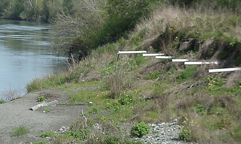
Exposed leach field. Photo:Thewellman, public domain.
In addition, 24 other instances have been identified in which large scale septic systems failure and ground water contamination may have resulted. There are surely other examples of large scale septic system failure across the U.S.
Septic System Design
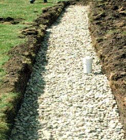
Drainage trench with PVC Riser
Effective design requires pre-treatment in a multiple chamber septic tank with an effluent filter to remove organics, suspended solids, grease, oils, etc.
Trenches should be 0.5 to 3 feet wide, excavated parallel to the surface or groundwater piezometric surface contours (based on analysis or ground water mounding potential) with level bottom surfaces.
Uniform dosing of the infiltration trenches four or more times daily, depending on soil type.
Multiple drain fields (three minimum) to allow annual or semiannual resting and standby capacity for operational flexibility.
Devices for monitoring daily wastewater flows, infiltrative surface ponding, ground water elevations, and plume contaminants at some downstream point. In the image above, an inspection riser is visible in a nearly complete infiltration trench.
Pre-construction testing of water quality and ground water elevation. Periodic testing of ground water quality below the drain field for comparison with initial values.
Study Questions
In the conventional wastewater treatment plant in which tank is activated sludge and aeration added to the water?
What is activated sludge and why is it added to water after the primary treatment phase?
List three inputs into the conventional waste water treatment plant that make this an expensive part of municipal infrastructure.
What are the BOD and TSS secondary treatment standard set by the U.S. EPA?
List two features of highly efficient septic tanks.
A septic tank must be large enough to allow retention of the raw sewage for at least _________ hours.
What percentage of private, small scale septic systems fail?
Mark Gross,.Wastewater Characterization. 2004
References
Mark Gross. Wastewater Characterization. 2004. http://onsite.tennessee.edu/BsE532/WW%20Characterization%20Text.pdf
Iowa Department of Natural Resources. Primary Treatment Units – Septic Tanks For Small Community Systems, Appendix A. http://www.iowadnr.gov/portals/idnr/uploads/water/wastewater/files/dg_app_a.pdf