Introduction
This section will present ways to contour the land to collect rainwater for infiltration into planting beds. This reduction in runoff deeply saturates the soil volume and makes more soil moisture available to plants later in the season.
In this section we will consider landscape rather that roof catchment areas. A catchment area is the zone that contributes water to a holding area. Of course, some of the landscape is made up of impervious surfaces, such as driveways and sidewalks which are part of the catchment area but planted surfaces can contribute water also, especially where soils have more that 30% clay or are steeply sloping.
Fine Grading for Water Conservation
Residental rainwater catchment. Image: Waterfall.
When we begin to calculate runoff rates and volumes in another tutorial, we will make the distinction between connected and disconnected impervious surfaces. All of the techniques illustrated below are ways to disconnect impervious surfaces from each other. That is the water from an impervious surface, such as a roof or driveway is directed through a landscaped area rather than to another impervious surface (including stormwater sewer pipes).
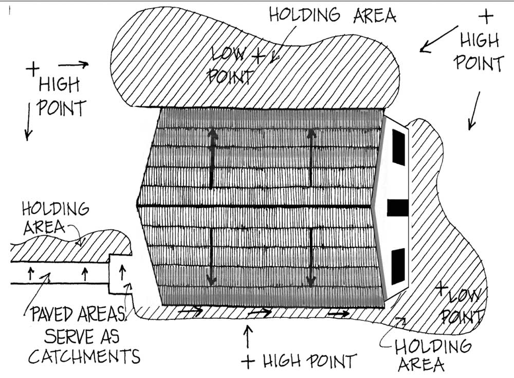
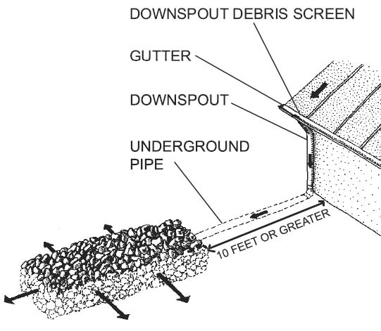
This diagram shows how a simple home rainwater harvesting system could be planned. This is really a fine grading plan that establishes a number of high and low point to direct water through swales to infiltration areas.
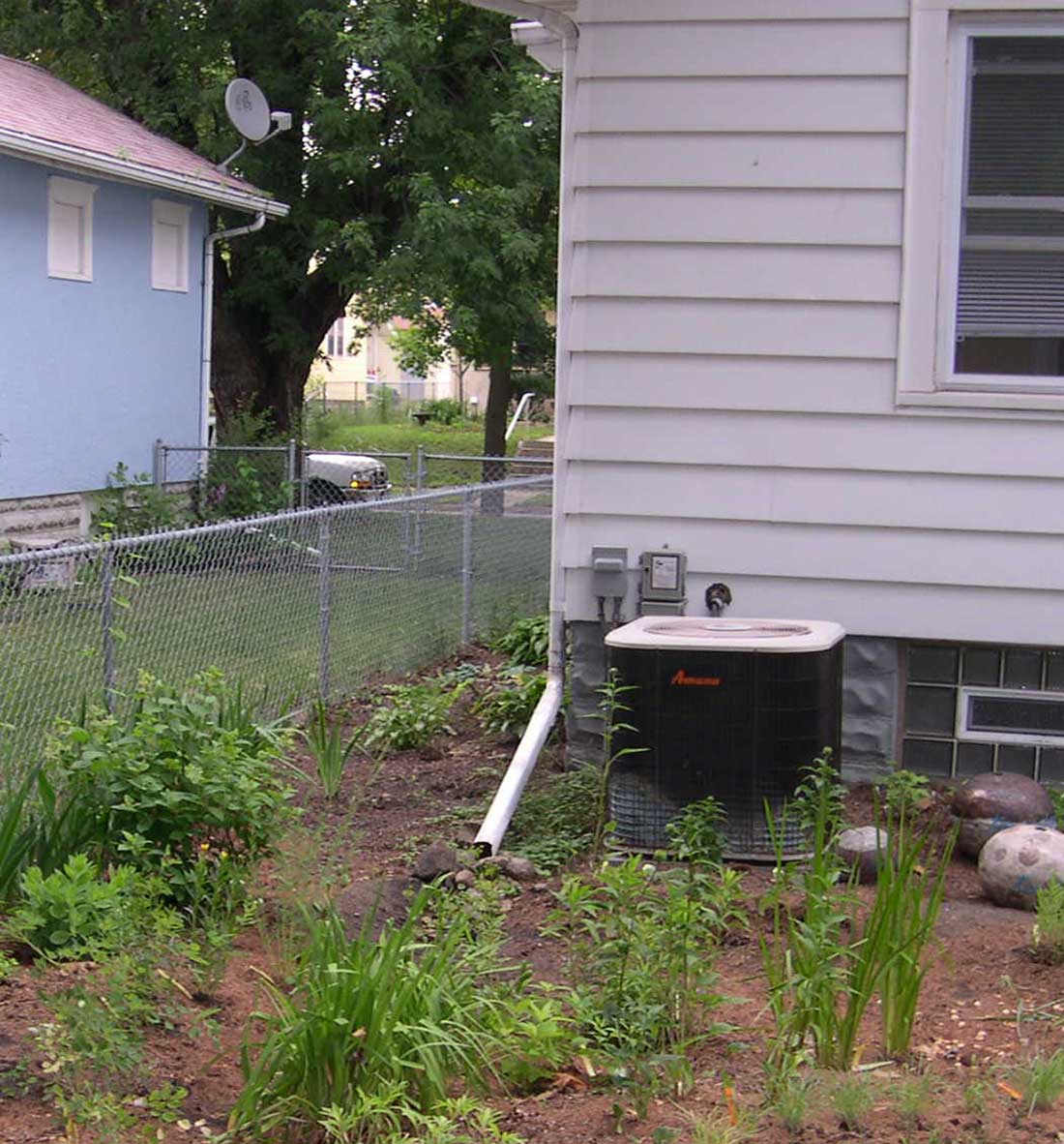
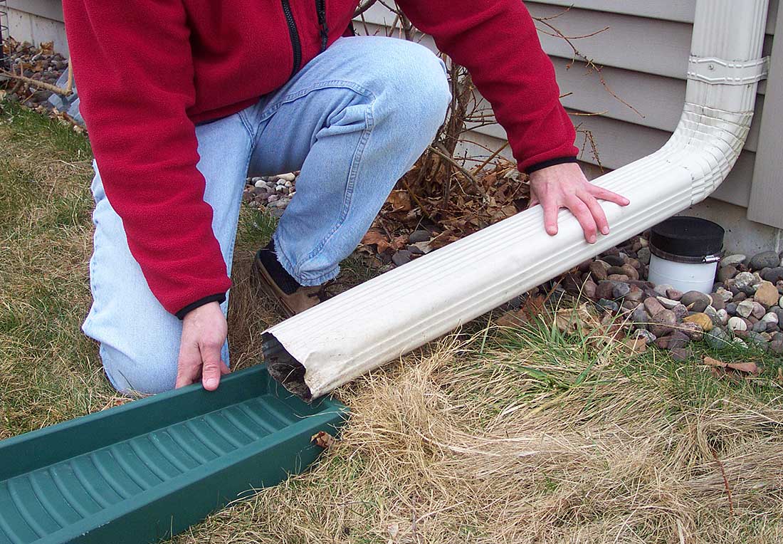
Left: Downspouts flood a planting area. Image: Brian Ash, license CC-by-SA 3.0. Right: Downspout disconnected from foundation drain, Image: www.bluewaterbaltimore.org
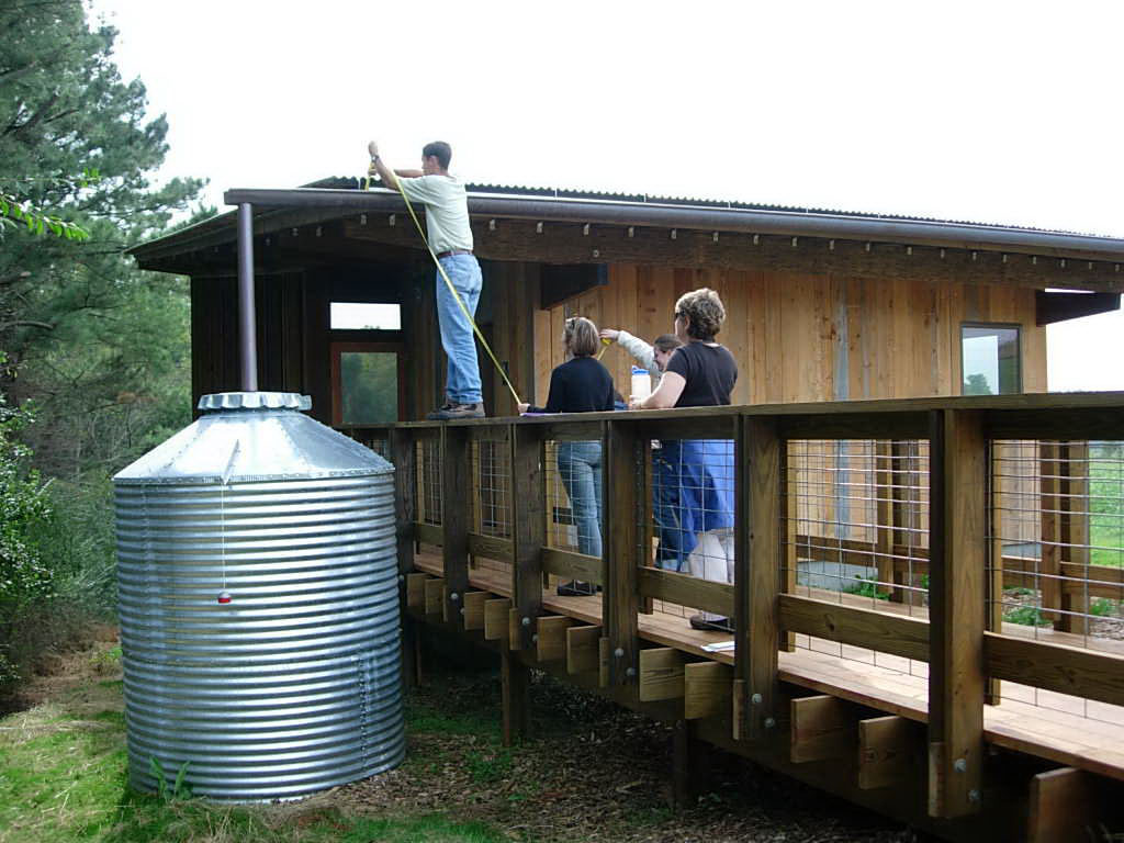
In these images, downspots at the building corners collect water from the roof gutter to flood a planting area near the building. This is in contrast to conventional construction where downspouts are connected to a foundation drain which is connected to the stormsewer in the street (connected impervious system). The downspouts need to be extended along the ground for a few feet to avoid saturating soil along the foundation. Alternatively, the downspouts can discharge water onto a splash plate that directs the water away from the foundation. Notice in the second image above that the douwnspout has been disconnected from the foundation drain which is capped. Very ornamental splash blocks are available to create landscpe accents instead of only functional infrastructure.
channel.gif)
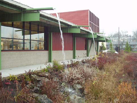
Left: Capturing water from buildings without gutters. Image: Waterfall. Right: Commercial and public buildings can be designed with scuppers that extend over walks to drain rainwater into swales.
This image (above left) shows a building with no roof gutter or downspouts. In this case the water falls from the eave into a swale that directs it to a planting bed further away from the roof. In both of these examples, the site must be nearly level.
Complex.gif)
Left: A hose delivers water to individual plants. Image: Waterfall. Right: Downspout fills a tank for later use in irrigation. Photo: NCSU - BAE
This is an example of a more complicated system where water is stored and filtered and then delivered to plants through pipes or hoses.
Crescent.gif)
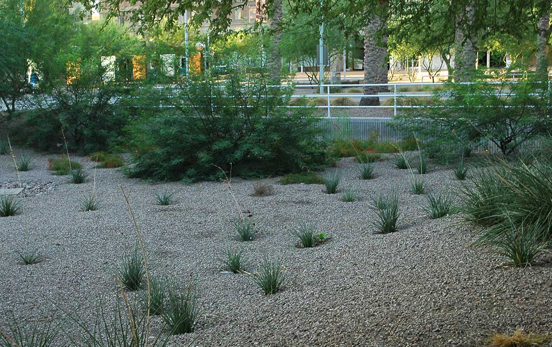
Left: Basins and check dams in sequence. Image: Univ. of Arizona Extension. Center: Crescent berms on sloping land. Right: In arid climates fine grading to create depressions can create conditions that allow an expanded planting palette. Photo: Austin, 2012.
Tree basins can be formed beyound their drip lines to hold water and can transfer water from tree to tree during large rain storms. This method is appropriate for an almost level site. Simple raised crescents along a slope can capture rainwater runoff. This method applies to a gently sloping site. Whether the water basin is a depression ofr form by a berm, the base of trees and shrubs should be at least four inches higher than the watering basins around them. Trees sensitive to soil fungi, like some drought tolerant oaks, or when planting trees in heavy clay soil, raising the tree well above the watering basin leads to better growth and health.
French Drains
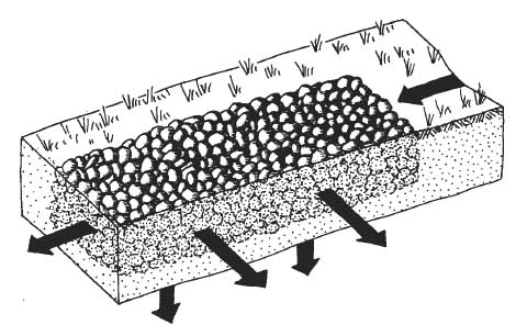
Image: Waterfall.
French drains are rock filled channels that slow and store water for infiltration. They are alternatives to the earth-only techniques shown above where the velocity of water is high due to steep slopes or heavy rainfall. It is important to prevent the French drain from filling with sediment. Often the trench is lined with a non-woven filter fabric before the rock is added to prevent this siltation.
![]()
Infiltration Trench. Images: Waterfall.
In many cases the French drain is a reservoir where water is held until it can infiltrate into the soil. This is often called an infiltration trench. In this image a perforated plastic pipe distributes water along the length of the trench. The pore space between the stones is the water storage area. Therefore, round drain rock (to about 2" diameter) rather than crushed aggregate should be specified for infiltration trenches. The porosity of 2" drain rock is 40%.
Dripline.gif)
Infiltraton through a field of french drains. Right: Exten basin 2' beyond the mature canopy. Image: Waterfall.
This cross section through a series of French drains suggests that their spacing should be based on the texture of the soil. A medium texture, such as loam, requires 3' - 4' between the edges of the trenches if the area between them is to be fully saturated by infiltration from the trenches. For rows of trees and large shrubs, the spacing between the French drains can be increased significantly. These large plants tend to collect most of the water they use from along or beyond their drip line. Tree basins should be formed two feet beyond their drip-line to contain most of the tree's roots. The basins should hold 4" of water.
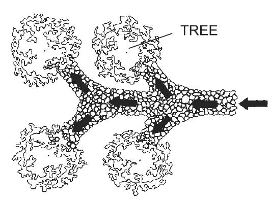
Image: Waterfall.
Here French drains are used a conduits ending at trees. The roots of different types of plants extend into the soil forming a root zone. This is 6"-12", 12"-24" and 18"- 36" for perennials, shrubs and trees respectively (Az Extension). Infiltration and irrigation goals are to saturate the root zone but not deeper. The table below (Stein, 2011) shows the general infiltration rate and the available moisture for three soil texture classes.
| Soil Texture | |||
|---|---|---|---|
| Sands | Loams | Clays | |
| Water infiltration rate (inches per hour) | 2.0 – 6.0 | 0.6 – 2.0 | 0.2 – 0.6 |
| Available water (inches per ft.) | 1.0 – 1.5 | 1.5 – 2.5 | 2.5 – 4.0 |
| Days to depletion when ET = .2 inches/day | 5 – 7.5 | 7.5 – 12.5 | 12.5 – 20.0 |
| Amount of water to wet to 12 in a dry soil (inches) | 1.0 | 1.5 – 2.0 | 2.5 |
In the table below (UC Extension) the approximate amount of water to infiltrate (or for irrigation to apply) is estimated based on rooting depth and soil texture. For trees (rooting depth = 3') the depth of water in a rapidly flooded basin would be 3.25" in order to saturate the root zone. This sort of rapid filling might occur when an impervious surface runoff is directed toward a landscape basin. When the basin fills the water should overflow to a second basin to avoid wasting the irrigation water by saturating more than the root zone.
| Inches of water to apply | |||
Root depth in feet |
Sandy Soil |
Loam soil |
Clay soil |
1 |
0.75 |
1.25 |
1.50 |
2 |
1.25 |
2.25 |
2.50 |
3 |
1.75 |
3.25 |
3.50 |
4 |
2.25 |
4.00 |
4.25 |
5 |
2.75 |
4.50 |
4.75 |
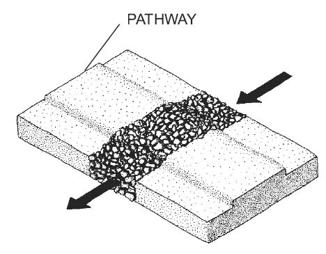
Image: Waterfall.
This image illustrates that French drains are not necessarily blocked by paths or even roads and parking lots. Water can flow in the drain under the paving. Soil or mulch paths are protected from erosion when water is directed across them by gravel drains.
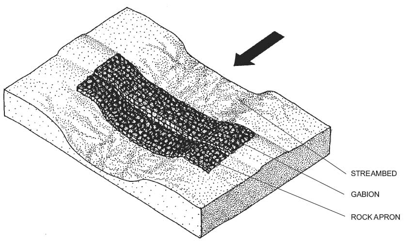
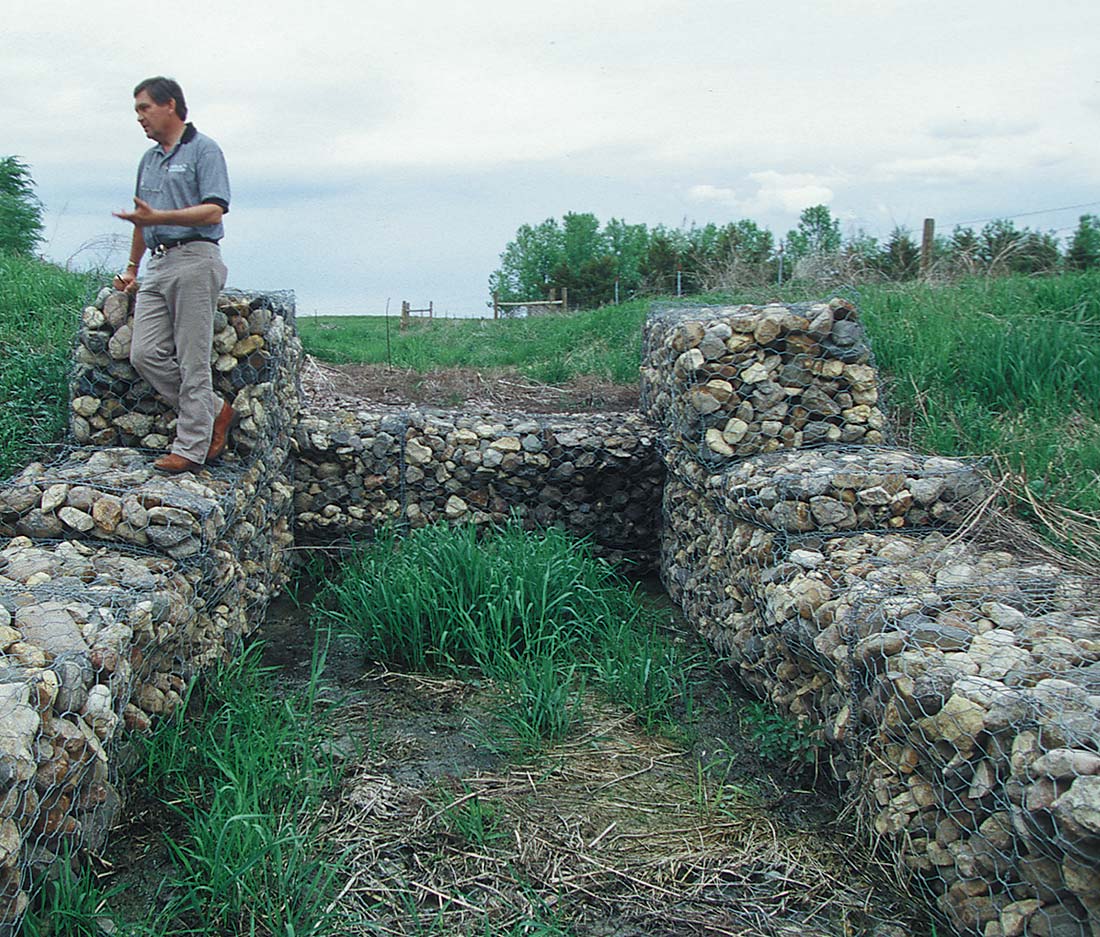
Gabions for landscape restoration. Image: Waterfall.
This drawing shows a gabion wall on a rock apron. Gabions are rock filled wire baskets. Chain link fencing is often used to make a wire container which is filled with large (6") stones. The gabion slows the flow of water causing sediment to drop to the bottom of the stream or gully. Over time, this techniqe repairs eroded gullies. In this image the rock base prevents erosion around the gabion.
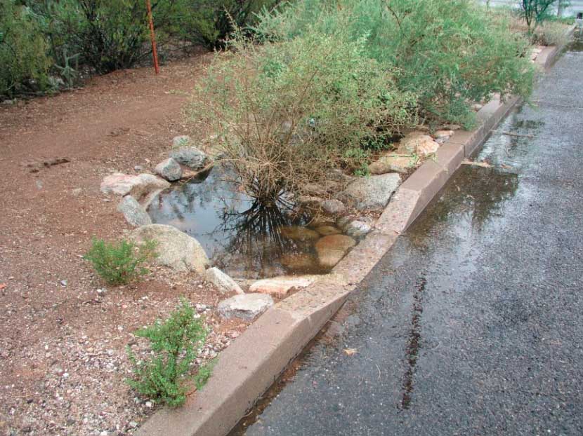
Image: The Nature Conservancy.
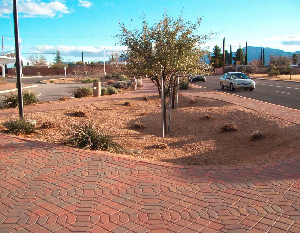
Hard, impervious surfaces such as parking lots are excellent catchments. This image shows the diversion of runoff to an open curb, allowing the water to flood the infiltration basins in an arid climate.
Micro-basins Image: Waterfall.
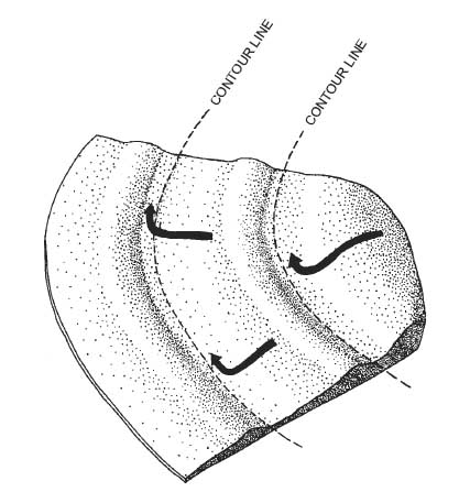
Here are more examples of the many techniques to create small and large scale earthwork to capture and concentrate runoff. These methods are best suited where rain not intense.
The first two images show micro-basins that could be fashioned around single plants or groups. The third image shows an exmple of capturing runoff in stages along a slope. The berms direct the water downhill and almost parallel to the contours.
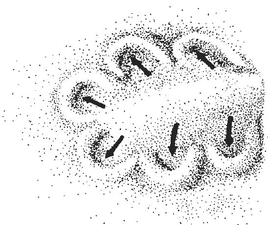
Ridge runoffImage: Waterfall.
In these examples of micro-basins a central ridge of soil or a walkway diverts runoff into the basins
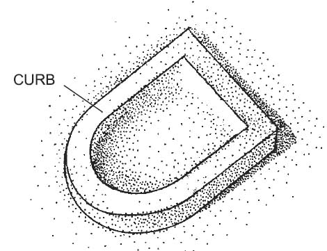
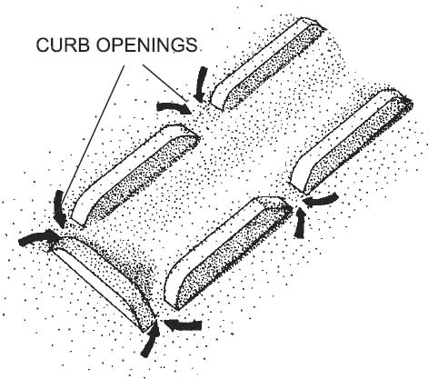
Natural or architectural basins Image: Waterfall.
Deliberate design during the development of the grading and drainage plan for a new site development can make use of curbs to contain and direct water to storage areas while accomplishing other design goals.
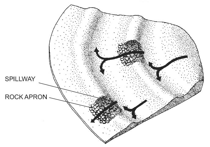
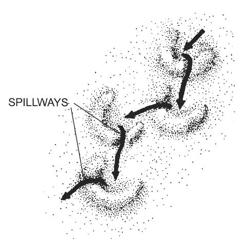
Curb cuts to direct flow to landscape basins Image: Waterfall.
This image shows a larger scale application where earth berms parallel to the contours and in series down a slope slow and contain hillside runoff. The rock aprons serve as erosion protected spillways. This design accommodates large storm events.
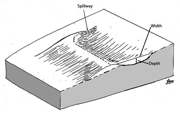
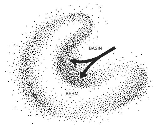
Hillside basin and berm. Image: Lancaster, 2007.
The berm shown in this plan view is similar to the one in the previous image. It is on a slope, includes a berm, a basin and a stone spillway. Enlarge the image to see that the spillway is lower than the top of the berm.
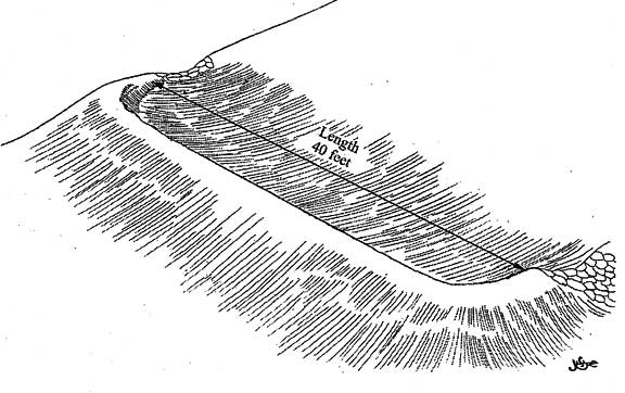
Hillside basin and berm. Image: Lancaster, 2007.
This view shows the full length of the berm which follows the contour of the slope.
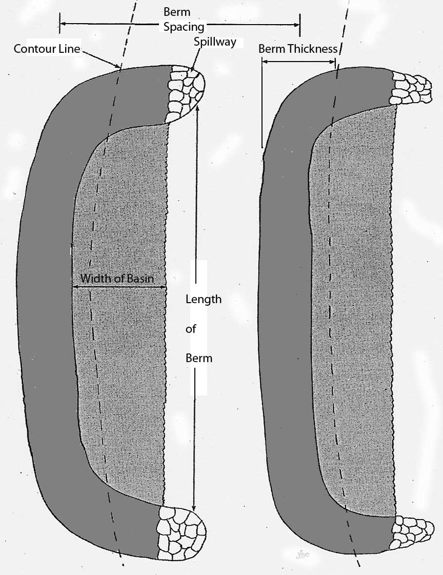
Image: Lancaster, 2007.
Image: Lancaster, 2007.
This section through an upper and lower berm shows the elevations of the water level, spill way and berm top.
It is possible to calculate the amount of water held in the basin or the amount held per liner foot of berm length.
First calculate the cross sectional area of the basin with the formula:
Area = 1/2 x width x depth
Then calculate the volume of the basin:
Volume = area x length
For example, if a basin were 10 feet wide, 2' deep, and 40' long then the volume would be calculated:
Volume = .5 x 10' x 2' x 40' = 400 cubic feet.
Since there are 7.48 gallons per cubic foot:
400 x 7.48 = 2,992 gallons
If we re-calculate the volume above but use 1' for the berm length instead of 40' we get:
Volume = .5 x 10' x 2' x 1' = 10 cubic feet for each foot of berm length.
To determine the spacing between berms we need some data. First we need the coefficient of runoff, and the rain depth from a design storm. For this example assume a C = .55 and a 2" rain depth converted to feet 2/12 = .17'. From the example above we will use 10 cubic feet as the volume. The spacing calculation is:
Spacing = (10 cf/lf of berm)
/ (.55 x .17) = 106.9 feet. The berms need to be place about 107' apart to contain the design storm.
Collecting water on slopes
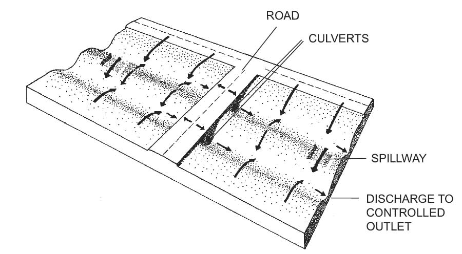
These images are a refinement of the technique shown above. They address the complications of roads and walks in a developed rather than natural context. Roads and walks can act as unwanted dams. Capturing runoff from steeply sloping sites is especially problematic. Ripping slopes and forming berms parallel to the contours can greatly assist in the establishment of container or hydro-seeded plantings.
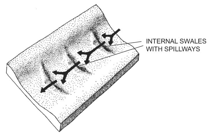
caption
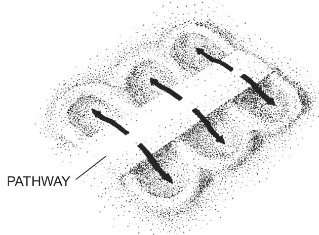
Swales are often the product of placing roads, drives and walks parallel to the contours. These shallow drainage shapes can be utilized to hold runoff rather than accelerate it (as is typical). Here impediments to rapid runoff are placed in series along the swale center line. Especially, just after construction good sedimentation control is required to preserve these landforms.
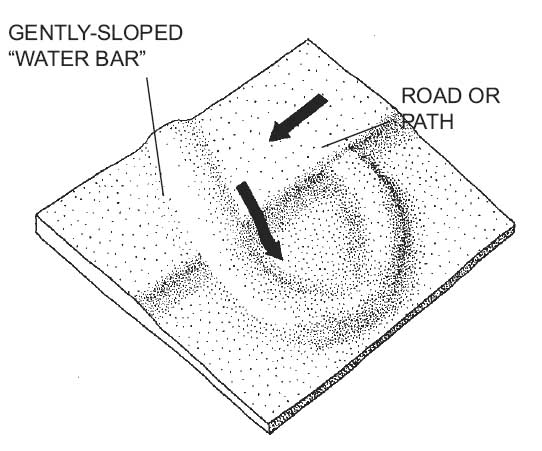
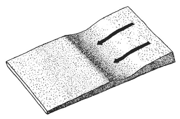
caption
You are probably familiar with water bars from hiking or driving on earth paths and roads in National Forests. Placed at an angle to the flow of water, the berm prevents water from accumulating and causing erosion. In this variation a J-shaped extension forms a storage pool on gently sloping land.
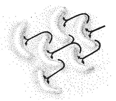
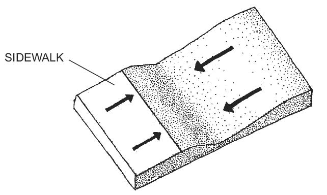
caption
Like the micro-basins viewed earlier, this series of earth forms collects and stores water from light and heavy rain.
Mulch
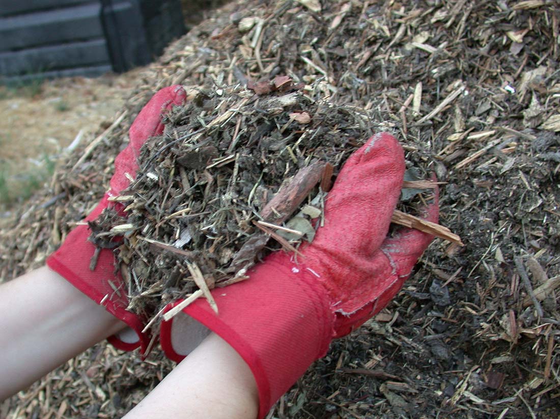
Shredded Yard Waste Mulch. Photo: Dvortygirl, license CC-BY-SA-3.0
The use of mulch can extend the effectivness of harvesting and infiltration of stormwater. The presentation above treated only collection, routing and retention of shallow depths of storm runoff, but some mulches absorb a significant amount of water. Some also facilitate a significant loss of moisture due to evaporation. Both absorbtion and evaporation are positive for the reduction of stormwater runoff.
In general, the mulches that absorb the most water are subject to the greatest evaporation losses. For example, a three inch depth of finely ground and composted yard waste absorbs .4" inches of water from a 1" rainstorm (or overhead irrigation application). The evaporation loss from this mulch is about half of the absorbed water over the course of 6 days (October in S. California) and a Evaproation-Transporation Stress of 75%. Mulch made from composted sewage sludge and finely ground bark or composed yard waste is highly absorbant (Shaw, 2005).
However, if water conservation during warm, dry weather is also a goal then evaporation of water from mulch can reduce the amount of water reaching plant roots. This leads to more water use to sustain the plants. Water loss due to evaporation and excessive water use is most problematic when irrigation is frequent (every 5 days or less), applied overhead (spray rather than drip) and a mulch with high absorbion and evaporation characteristics is used. Coarse uncomposted mulches such as shreaded or chunks of bark retain less water (.28" for a 3" depth of mulch) and allow less evaproation. Test of irrigation water use revealed the greatest demand from landscapes with no mulch. Even fine mulch reduces irrigation demand but the best performing landscape included coarse, uncomposted mulch (Shaw, 2005). Water use can be reduced when any type of mulch is used if the time between irrigation applications can be extended. For drought tolerant plants shifiting from a 5-day interval to a 7-day results in significant water savings.
Evaporation is usually of concern in summer when supplemental irrigation is added to sustain plants in the human environment. However, especially in the Western U.S., evaporation in winter is an often neglected factor in stormwater management. In Idaho the winter Evapotranspiration is, .07" Nov.; .04" Dec.; .06" Jan.; 1.0" Feb.
Site Planning for Harvesting Water from the Landscape
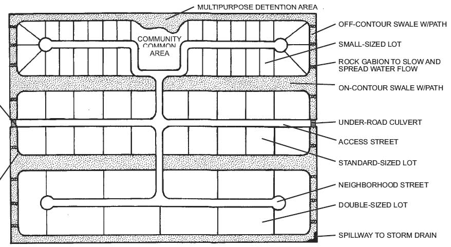
Subdivision plan. Image: Waterfall.
Development of residential and commerical parcels includes site grading plans. However, these plans often ignore the fine grading required to capture water for infiltration and use by the proposed plants. The image above and those that follow show a sequence of planning studies leading to better utilization of water on-site. You will apply these methods to the planning for your semester project. The image above is a subdivision plan illustrating the opportunities to store runoff.
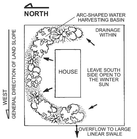
Runoff concept for a single parcel. Image: Waterfall.
A single lot in a subdivision can address runoff flow and storage.
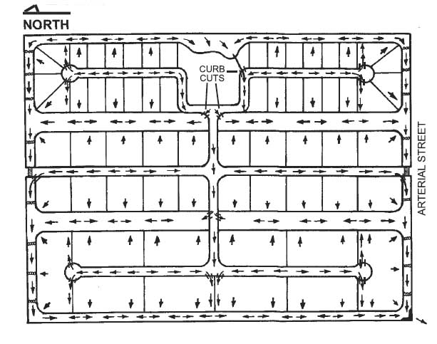
Flow routes. Image: Waterfall.
This subdivision plan illustrates the flow routes.
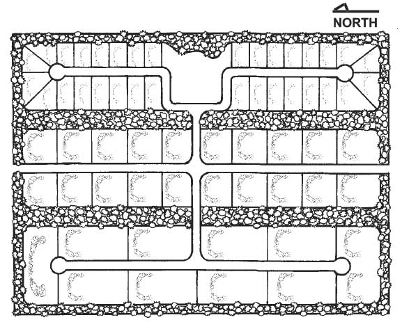
Landscape forms. Image: Waterfall.
The plantings are shown in a subdivision to take advantage of the harvesting system.
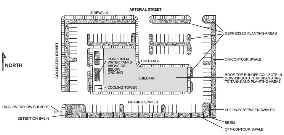
Commercial plan. Image: Waterfall.
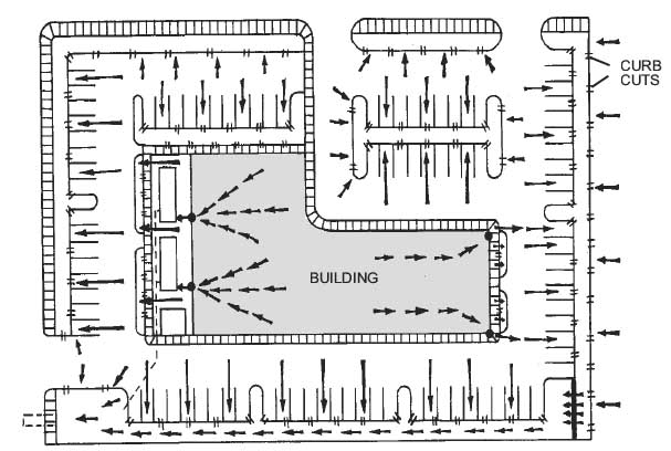
Flow routes. Image: Waterfall.
The flow diagram is always a first step in developing a drainage concept and subsequent grading plan.
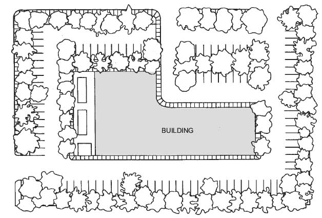
Planting concept. Image: Waterfall.
Commercial application - Planting
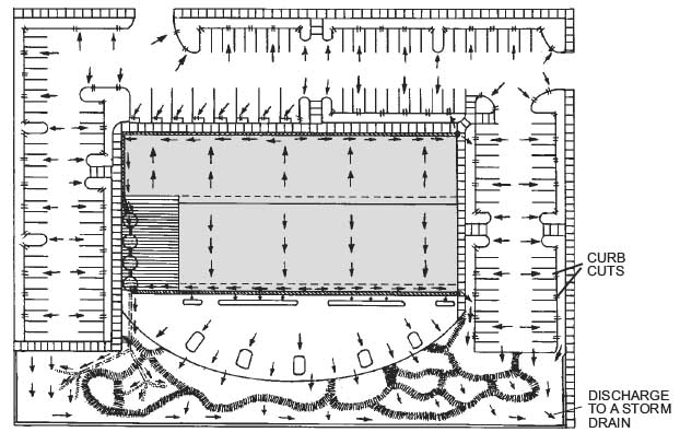
Image: Waterfall.
Public building present many of the same problems and opportunities as commercial project. This image shows the flow diagram.
Study Questions
True/False. The techniques in this tutorial disconnect impervious surfaces.
What is the porosity of 2" drain rock?
How far beyond their drip lines (canopy) should tree catchment basins extend?
Be able to calculate the volume of water held behind a berm on a slope.
Be able to calculate the spacing of berms on a slope.
How much water does a 3" depth of a finely ground, composted yardwaste mulch absorb from a 1" rainfall?
Which mulch would you choose to absorb and evaporate a large quantity of stormwater.
How much water is lost to evapotranspiration in January in Idaho?
References
City of Bellingham. 2012. Rainwater Harvesting. http://www.cob.org/documents/pw/environment/water-conservation/rainwater-harvesting-booklet.pdf
Lancaster, Brad. 2007. Rainwater Harvesting for Drylands and Beyond Vol. 2. Rainsource Press.
Shaw, David A.; Pittenger, Dennis R.; McMaster, Mark. Water Retention and Evaporative Properties of Landscape Mulches. Irrigation Association, 2005. http://ucanr.edu/sites/UrbanHort/files/80238.pdf
University of Arizona Extension. 2002. Watering Trees and Shrubs. http://ag.arizona.edu/pubs/water/az1298/
University of California Extension. Water and Soil. No Date. http://ceventura.ucanr.edu/Com_Ag/Subtropical/Avocado_Handbook/Horticulture/Water_and_Soil_
Stein, Larry. 2011. So What Constitutes An Effective Rain Event? Texas A&M University. https://aggie-horticulture.tamu.edu/earthkind/drought/drought-management-for-commercial-horticulture/so-what-constitutes-an-effective-rain-event/
Waterfall, Patricia. Harvesting Rainwater for Landscape Use, University of Arizona Cooperative, Retrieved from http://ag.arizona.edu/pubs/water/az1052/harvest.html on March 10th, 2005 Rainwater Harvesting for Drylands by Brad Lancaster, 2009