Introduction
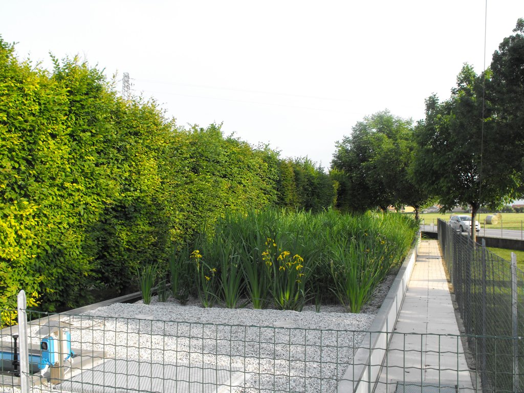
Horizontal subsurface constructed wetland treating swine waste, Italy. Photo: D. Tocchetto, 2010.
This tutorial presents the first of three types of wetlands constructed to treat domestic sewage (and agricultural wastewater). The quality of the water treated by these biological systems is as good or better than that produced by conventional wastewater treatment plants.
Types of Treatment Wetlands
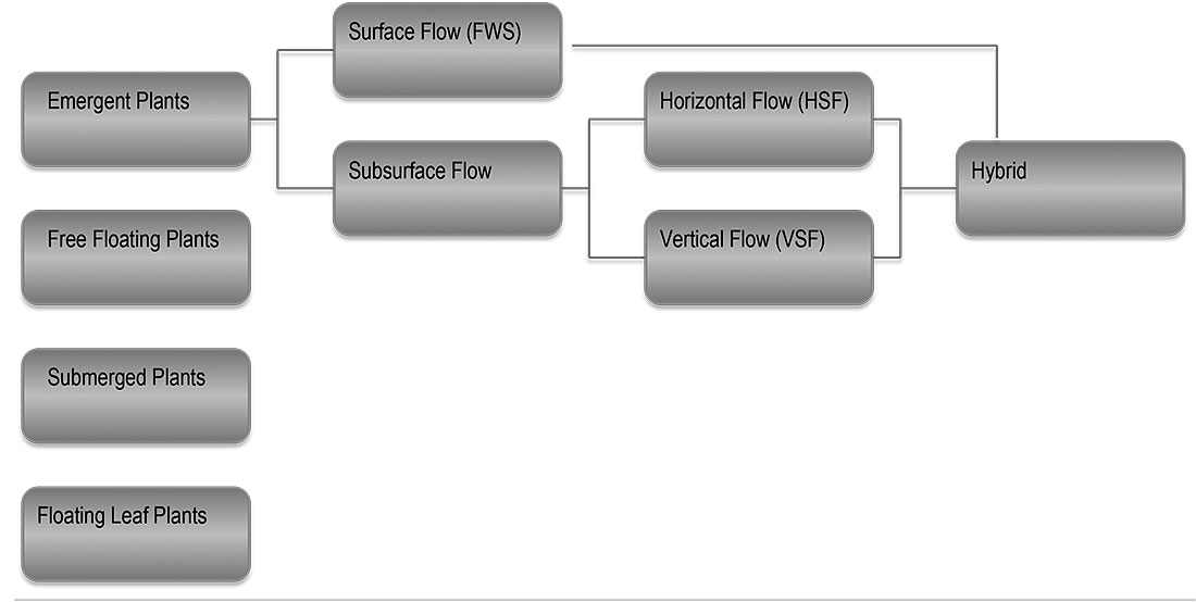
Types of Constructed Wetlands
There are several types of wetlands that are effective for the treatment of domestic sewage. However, most of the recent research and monitored wetlands are one of three types, although, increasingly these are used in combination. Enlarge the image above to see the possible wetland types (left) and the three types used for wastewater treatment (Vertical and Horizontal Subsurface wetlands and Free Water Surface wetlands). We will consider the horizontal subsurface flow wetland (HSF) first.
Horizontal Subsurface Flow Treatment Wetland
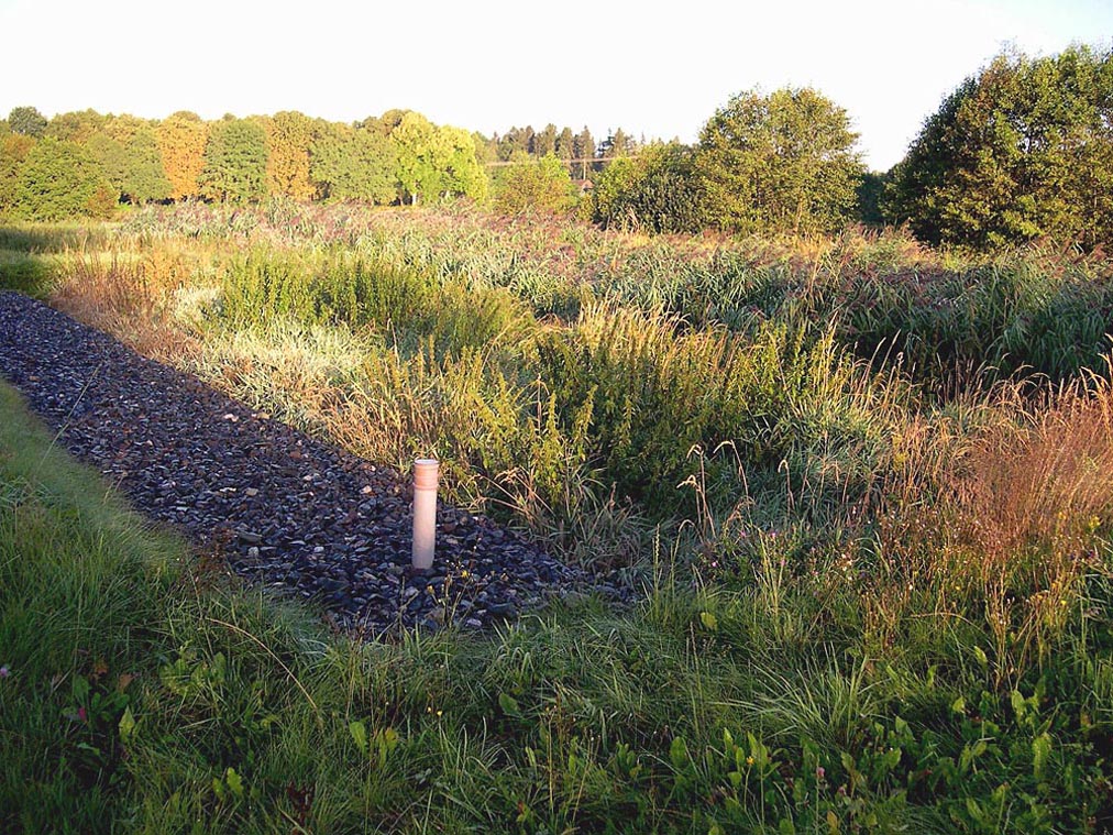
HSF Wetland in the Czech Republic. Photo: Jan Vymazal.
Subsurface flow wetlands are common in Europe where tens of thousands are used to treat domestic wastewater for small communities. About 50 square feet (4.5 square meters) of wetland area per person served is required to meet EPA secondary treatment standards in summer and winter (Vymazal, 2005). The HSF wetland is less sensitive to cold weather than the Free Water Surface wetland and is easier to insulate. A Minnesota HSF wetland is insulated with 6” of mulch to protect it from freezing at temperatures as low as -45°F (Kadlec, 2009). In Norway, HSF systems preceded by a buried bio-filter have proven to be very effective (Jenssen, 2005). In the HSF wetland there is no standing water on the surface, so there is no odor or contact hazard, but, like the FWS wetland, the bed is densely planted making it an open space feature.
Critical Elements
Horizontal Subsurface Flow Wetland (left), Vertical Flow Subsurface Wetland (right)
A – Inlet from septic tank; B – Horizontal flow through medium to fine gravel; C – Recirculation of 50% of the flow from VSF to HSF wetland for de-nitrification; D – Collection zone, coarse gravel; E – Water level control; F – Intermittent dosing of VSF; G – Water drains vertically through gravel to bottom drain; H – Outflow to free water wetland; I – Dense planting. Austin, 2009
Several factors are critical to the effectiveness of HSF wetlands, including gravel size, uniform flow, and dense plant coverage. Pre-treated wastewater (from a septic tank) must be evenly distributed through a coarse gravel inlet trench by a perforated pipe (A in the section above). In early designs, the distribution pipe was above ground but this caused algae clogging problems. Placing the distribution pipe a below grade, but above the elevation of the outlet collection pipe, reduced clogging and maintained a hydraulic gradient through the bed.
Water flows slowly through the gravel that is 24”-30” deep. Most HSF wetlands consist of a 6’ wide inlet and outlet zone ( A and D) composed of 1 ½” – 3” diameter gravel and a main bed (B) composed of gravel .8 – 1.2” in size. The gravel size limits clogging but provides a high surface area for biofilm growth. The size of the gravel in the main bed varies according to the shape of the wetland and the organic loading rate. There is no longitudinal slope on the bottom or the top of the bed (Wallace, 2006).
Beneficial bacteria growing on the gravel and roots use many contaminants in the water. The plant roots must reach all the way to the bottom of the bed. If they do, then the amount of ammonia removed will increase (Vymazal, 2005).
Secondary treatment can be accomplished if the water moves through a gravel bed for two days. Three days of residency time (this is also call hydraulic Residency Time, HRT) is generally required to achieve the maximum removal of pathogens. The HSF wetland is very effective at reducing BOD and TSS to achieve secondary treatment water quality. HSF wetlands are moderately able to convert nitrates to nitrogen gas but are ineffective at converting ammonia to nitrate and removing phosphorus unless a special media is used.
Performance of Horizontal Flow Constructed Wetlands
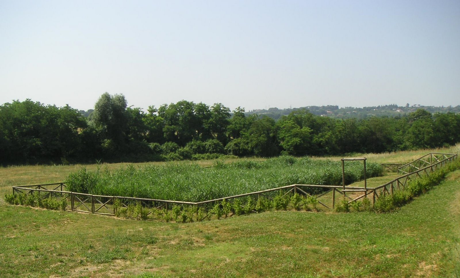
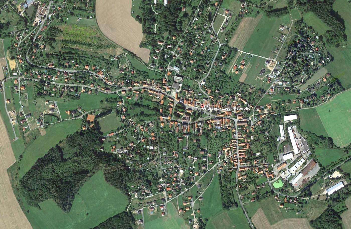
Left: HSF wetland at the scale of the village. Photo: D. Tocchetto. Right: the town of Ondrejov, Photo: Google Earth 49°54'13.19" N 14°47'10.12" E.
An example of a subsurface flow constructed wetland is a system to treat wastewater in the town of Ondrejov, Czech Republic. Built in 1991 to serve 362 people, the HSF constructed wetland covers 8675.7 ft2 (806 m²), representing 59 Ft2 (5.5 m²) per person, and treats 14,873 gallons (56.3 m³) per day. It is densely planted with Phragmites australis.
Monitored from 1991 through 2004, this wetland achieved an average BOD of 18.3 mg/L and TSS of 8.3 mg/L. The removal of phosphorus was low but continuous over the study period. Removal of ammonium was only 14.8% but nitrate removal was better at 41% (Vymazal, 2009), suggesting low oxygen in the wastewater. However, phosphorus, ammonia and nitrate are not regulated for secondary treatment in the Czech Republic or in the US, except when receiving waters are sensitive or severely degraded. A second HSF constructed wetland serving 1,400 people in another Czech town, for a similar duration, demonstrates similar performance (BOD = 4.6, TSS = 9.5, ammonia removal = 19%, nitrate removal = 40%, phosphorus removal = 7%) with very little reduction in effectiveness over time (Vymazal, 2011).
Little Stretton
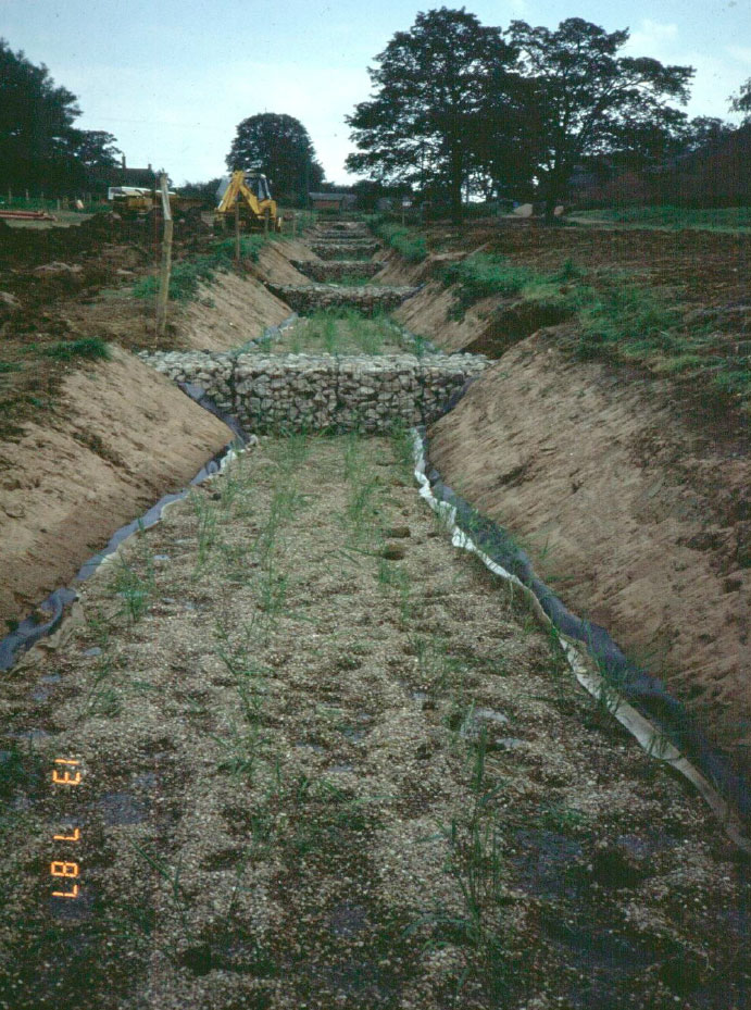
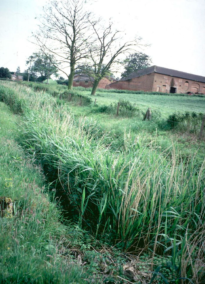
Left: HSSF wetlands immediately after planting in June 1987. Right: The same wetlands in November 1987. Photos: Paul Cooper.
The wetlands in the Czech Republic featured a single horizontal subsurface flow wetland cell, while in Little Stretton, United Kingdom a treatment system was built to serve 40 people and two farms and featured eight horizontal flow beds situated on a sloping site. The linear configuration of the wetland cells is not optimal but the several terraces improve water distribution (above left). Notice that the cells are about 6' wide and 48' long and separated by limestone gabbions.
Although BOD and TSS concentrations (7.3 mg/L and 16 mg/L, respectively) were similarly low in the outlet, much better reduction of ammonia (85.1%) was achieved due to better oxygen transfer among the beds due to aeration of the water as it moved between beds down the slope. Conversely only 16.4% of the nitrate and nitrite concentration was removed since that requires an anaerobic environment (Cooper, 2009).
The Little Stretton was an early constructed wetland experiment. If the Little Stretton project was built today, the cells would be wider and shorter. The bottom of the cells would be level with a vertical drop between the cells. The are of the wetland would be increased from 3 to 5 square meters per person.
The long experience with horizontal flow wetlands in Europe, as demonstrated by the Czhec and British example above, demonstrates the long term effectiveness and reliability of this technology.
Performance of HSSF Compared to Other Constructed Wetland Types
![]()
![]()
The tables above compare the performance of the HSSF wetland with the other types. Left: Performance for BOD and TSS. Right: Performance for nitrogen and phosphorus.
Legend: Treatment efficiency (Eff, in %) of various types of Inflow (In) and outflow (Out) concentrations in mg/L. HLR = hydraulic loading rate (cm/d). N = number of constructed wetlands. Source: 2010.
In the enlargement of the first table you can see the average performance of hundreds of wetlands. You can see that the performance of the HSSF wetlands discussed in the Czech Republic and England had much better performance for BOD and TSS that the average figures reported here. This shows that the technology is improving to provide better results. Notice also (in the second table) that the performance of the HSSF wetland is lower for removal of Ammonia than for other types of wetlands although removal of total nitrogen is comparable.
Horizontal Subsurface Gravel Wetlands for Stormwater Treatment
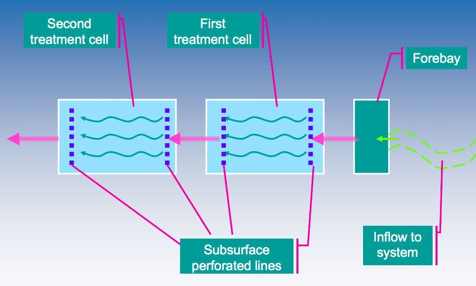
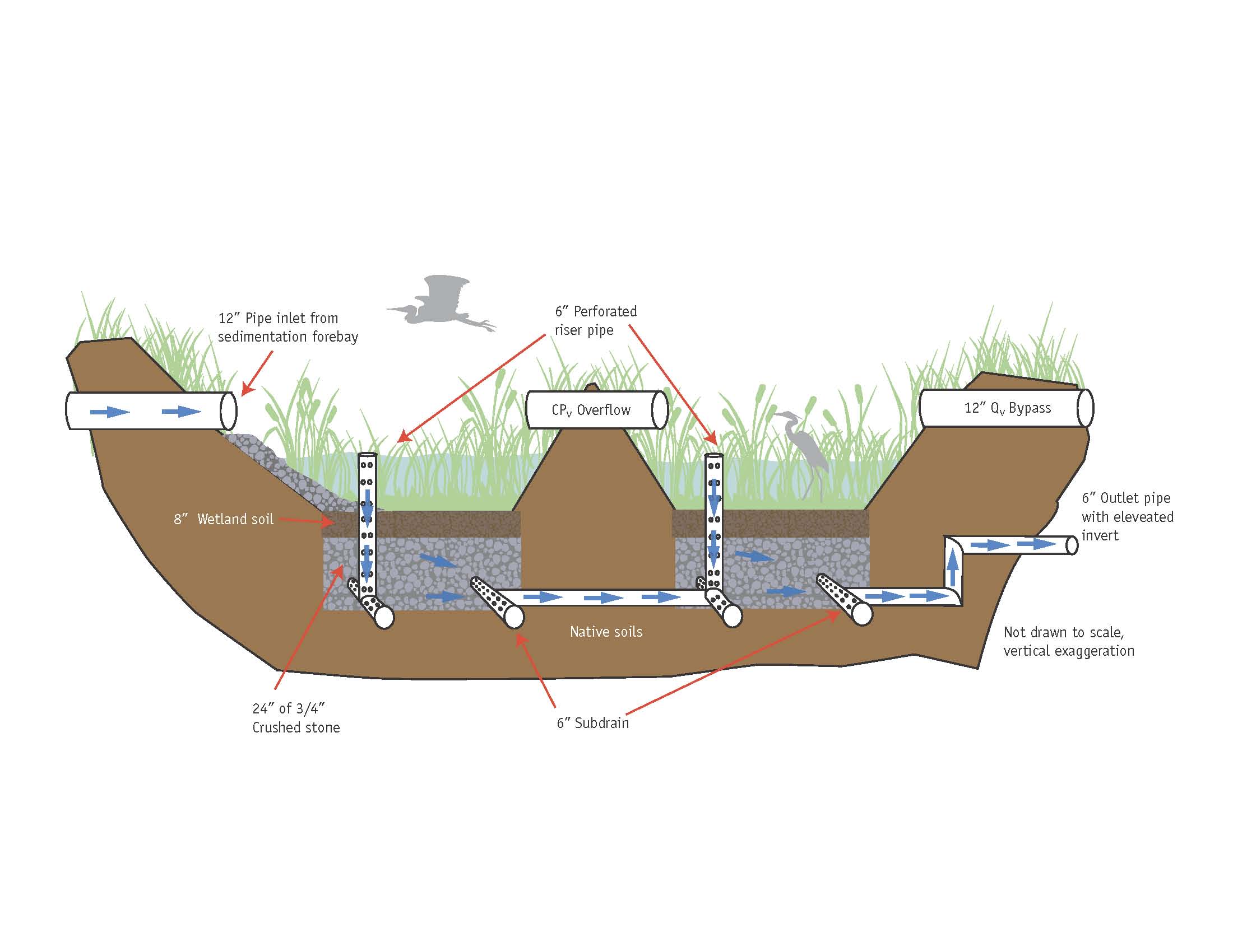
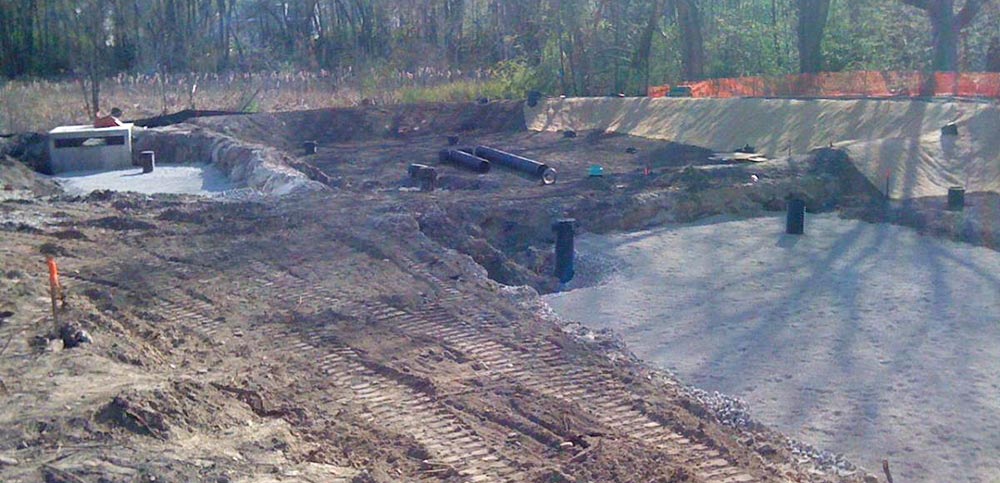
Left: An adaptation of the HSSF wetland for stormwater treatment was constructed by the University of New Hampshire Stormwater Center. Right: Section of the constructed wetland. Images: University of New Hampshire Stormwater Center, 2012.
Stormwater treatment is problematic due to the inconsistency in flow. This characteristic requires a modified HSSF design. The diagram, above right, shows a three cell stormwater treatment wetland constructed at the University of New Hampshire. The cells are separated by berms and the distribution pipes are 6" diameter perforated PVC.
While similar in appearance to the horizontal subsurface flow wetlands presented above, you can see in the second image above that a 1' deep temporary pool is provided above the surface of the soil. This is similar to a detention pond. However, notice that vertical drains deliver water to the gravel treatment bed as in a HSSF wetland. While the surface is dry between storms, the subsurface storage reservoir, filled with gravel, remains saturated and becomes anaerobic. This feature promotes denitrification (removal of nitrates).
The gravel bed is 24" deep and filled with 3/4" crushed rock. The wetland soil place above the gravel bed should be at least 8 inches thick. The soil and gravel bed should be separated with a 3" layer of pea gravel (1/4" diameter) as a texture transition. All layers should be constructed with a surface surface slope of zero. The surface infiltration rates of the wetland soil should be low. The hydraulic conductivity should be 0.1-0.01. ft/day. The soil below the gravel bed should be clay or a HDPE liner should be used to prevent infiltration. Once the water is treated infiltration in another cell might be desirable.
The wetland soil can be created by using the following formula.
Performance of the University of New Hampshire Gravel Wetland
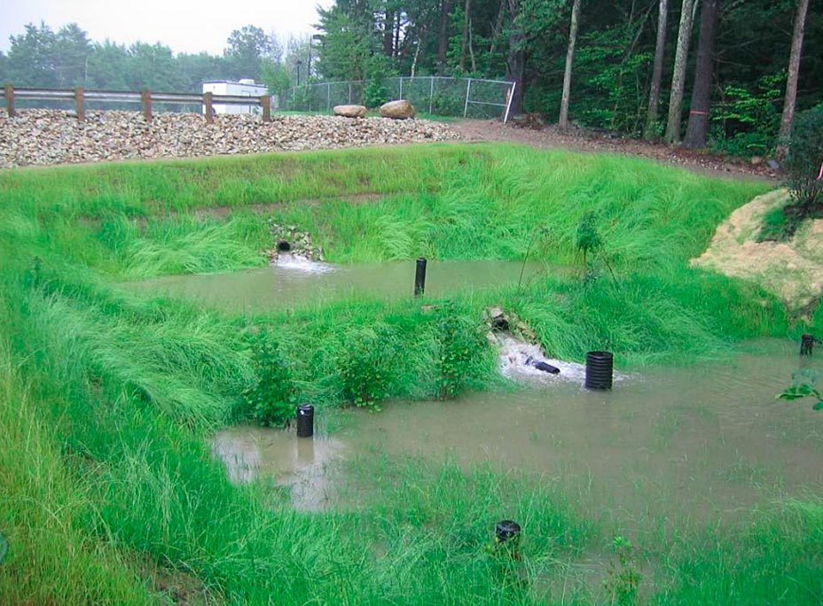
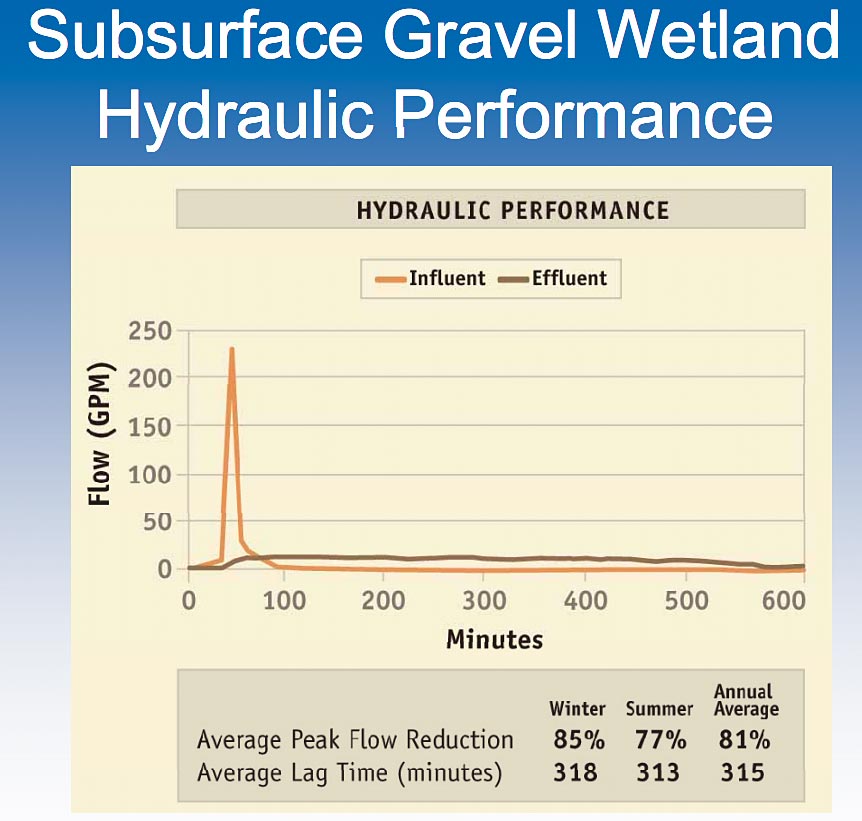
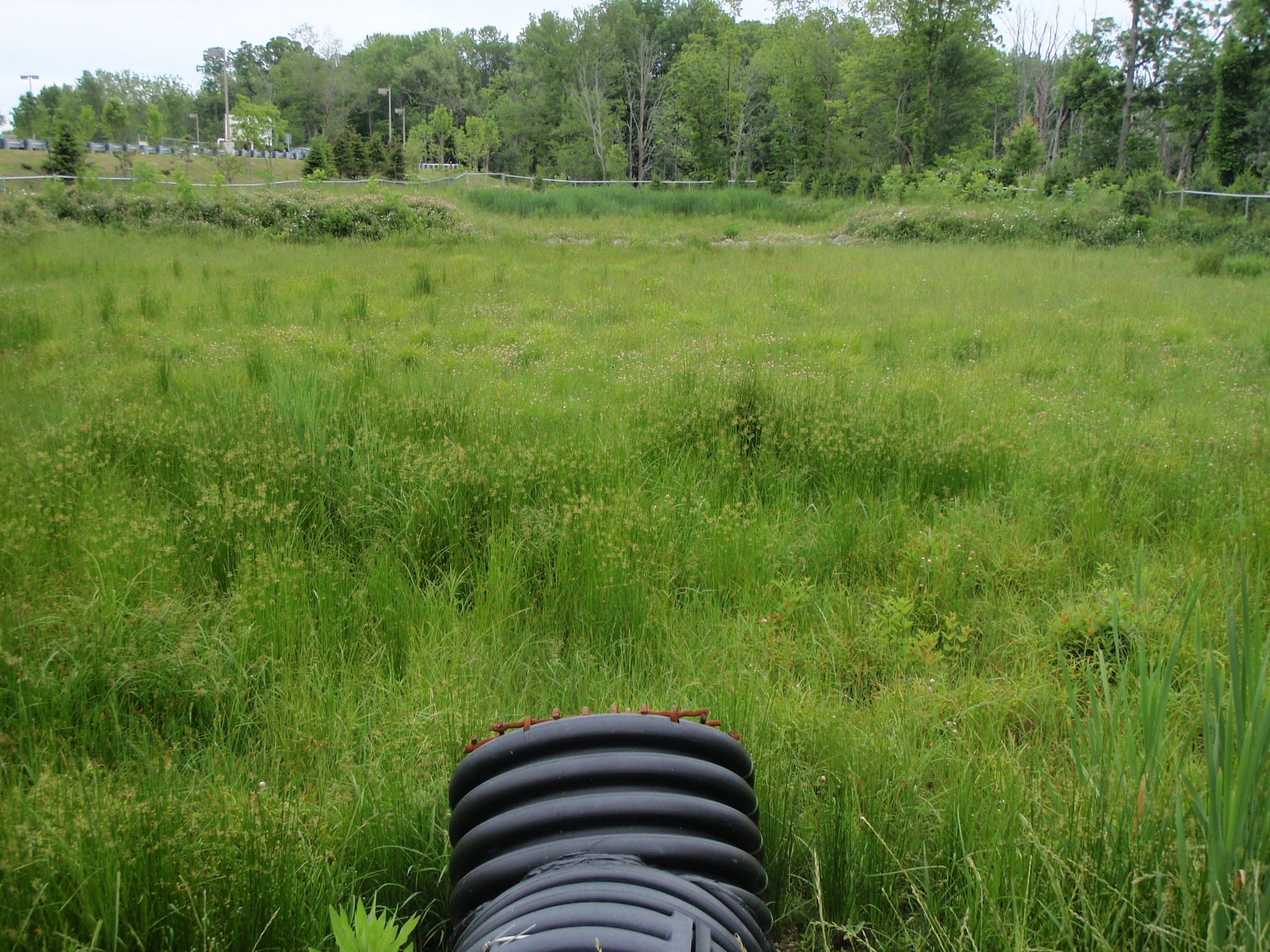
Left: The UNH gravel wetland test facility. Center: Hydrologic performance of the UNH gravel wetland test facility. Right: Treatment performance of the UNH gravel wetland test facility. Images: University of New Hampshire Stormwater Center, 2012.
The gravel wetland built at the University of New Hampshire collects water from an acre of parking, above left. Enlarge the center image to see the outstanding performance of the wetland in delaying the runoff and reducing its peak.
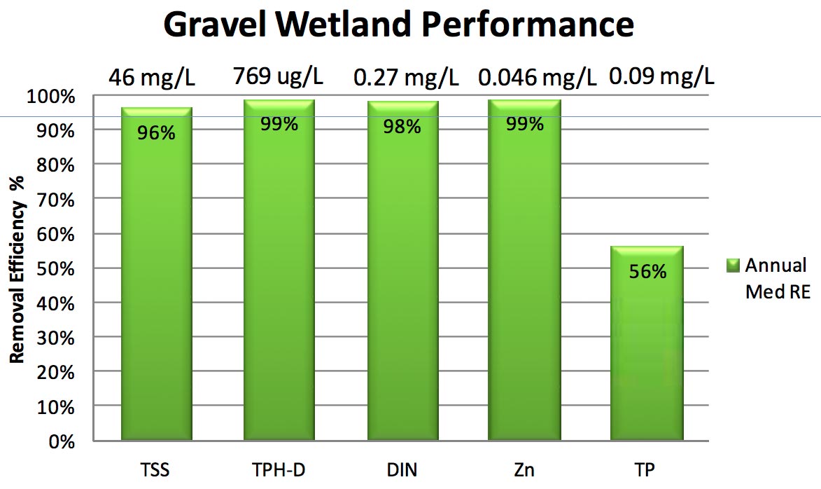
The third image shows the treatment performance of the wetland. In the chart TPH-D stands for total petroleum hydrocarbons and diesel and DIN stands for dissolved inorganic nitrogen (nitrite + nitrate + ammonia).
Greenland Meadows
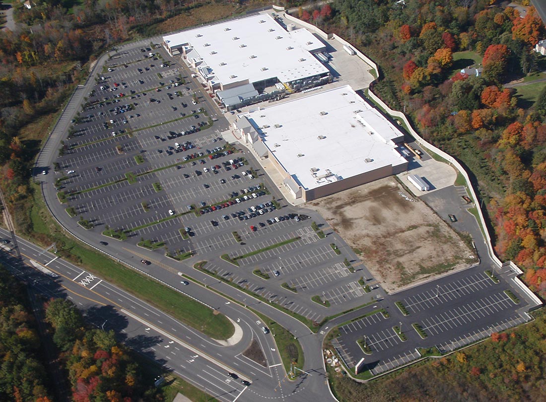
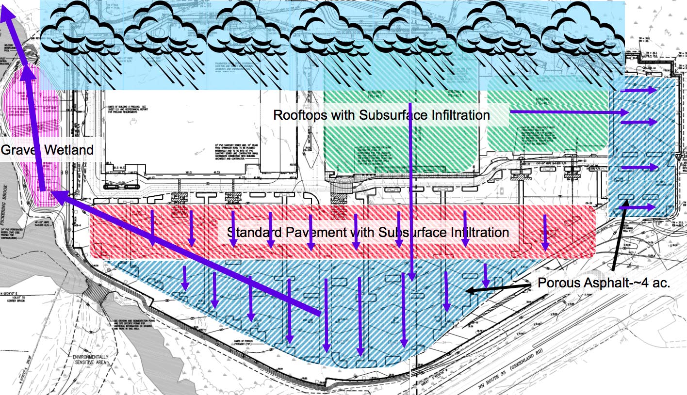
Left: Adaptation of the HSSF wetland for stormwater treatment for the Greenland Meadows shopping center. Center: Section of the constructed wetland. Right: Aerial view. Photos: University of New Hampshire Stormwater Center, 2012.
The aerial view (above right) shows a shopping center site. Notice the darker colored parking lot paving. This is permeable asphalt. The constructed wetland is at the upper center of the image. The development is located on a 55.95-acre parcel and includes three, one-story retail buildings (Lowe’s Home Improvement, Target, and a supermarket), paved parking areas consisting of porous asphalt and non-porous pavement. The total impervious area of the development – mainly from rooftops and non-porous parking areas – is approximately 25.6 acres. The two porous asphalt areas covering a total of 4.5 acres. The development is located immediately adjacent to Pickering Brook, an impaired waterway, according to the EPA. The two porous asphalt drainage systems – one in the main parking lot and one in the eastern parking area – serve to attenuate peak flows, while the aggregate reservoirs, installed directly below serve as storage for an underlying sand filter. Runoff from the sand filter, which itself provides extended detention and filtration, flows through perforated under-drain pipes that converge at a the gravel wetland on the west side of the site. The second image above shows the drainage design.
Paving costs were estimated to be considerably more expensive (by $884,000) compared to a conventional development, because of the inclusion of the porous asphalt, and stone reservoir layer. However, design that was implemented saved $71,000 in earthwork costs as well as $1,743,000 in total stormwater management costs. Overall, comparing the total site work and stormwater management cost estimates for each option, alternative that was built saved the developers a total of $930,000 compared to a conventional system of stormwater sewers and detention basins.
Performance
Interior
Average nitrate removal in gravel wetland systems is greater than 75% annually and 85% in the summer. The wetlands remove more than 95% of total suspended solids and have a phosphorus removal efficiency of 58%. As the table shows, the effluent from the gravel wetland is cleaner than the receiving stream. The exception is the level of salt. This is from deicing chemicals used on the parking and sidewalks.
Parameter |
Wetland Effluent |
Pickering Brook |
TSS |
3 mg/L |
53 mg/L |
TN |
0.50 mg/L |
1.35 mg/L |
TP |
0.005 mg/L |
0.145 mg/L |
Residential Wastewater Treatment
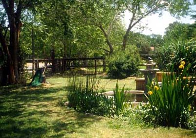
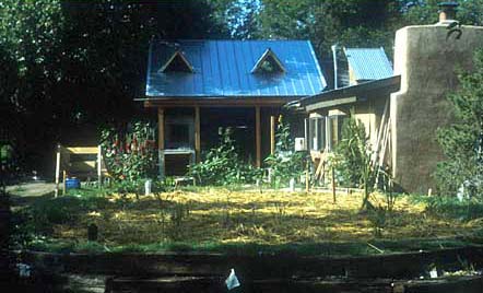
Completed System
By way of introduction, this is a residential scale sanitary wastewater treatment project case study. The project was designed and constructed by Paul Lusk in 1998. Mr. Lusk is a retired professor of Architecture at the University of New Mexico.
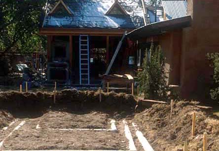
Basin
Primary effluent (after initial treatment in a septic tank) was directed to a subsurface wetland. In this image you can see the basin is dug. The pipes are part of a passive cooling and heating system that is not part of the wetland project
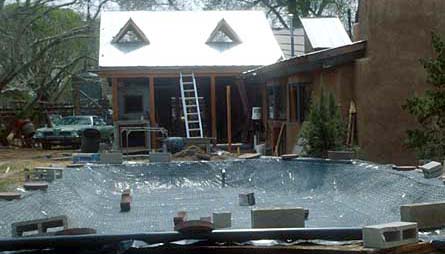
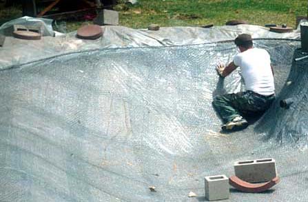
Liner
A waterproof shell is needed to prevent infiltration of the contaminated water. In this image three layers of wire mesh are placed in the earth basin. Concrete is then troweled into the mesh. The mesh holds the form, reinforces the concrete and distributes temperature evenly throughout the shell to minimize cracking.
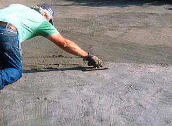
Finishing the concrete liner
Three layers of concrete are needed to achieve the thickness and texture required.
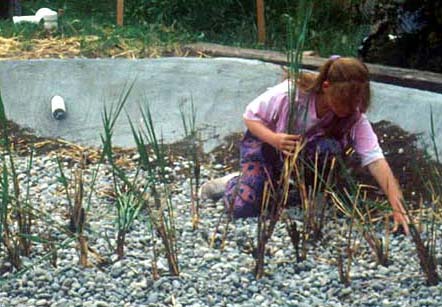
Planting
A layer of sand and a layer of gravel (some designers use small rubber chips instead of gravel) are added to the basin shell. Then the wetland plants are added.
Plant establishment
This image shows the wetland after planting. The straw visible in this image was added to keep the plants cool while they were getting established.
Collection Pool
After the wastewater flows through the wetland it drains into a free water pool to finish treatment and for evaporation (In this project there is no discharge of water off site. The water is used for drip irrigation or it evaporates.) In this view the pond is receiving the same wire and concrete treatment as the wetland basin.
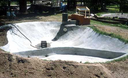
Collection Pool
This is the pool shell completed. You can see the inlet piping on the right side. The foreground tray is intended to provide the correct water depth for particular aquatic plants.
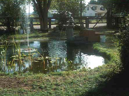
Evaporation Pond
This is an image of the finished pond. Notice the ornamental jet in the pond and the fountain at the pond edge. These increase evaporation and add aesthetic interest.
Here is a list of aquatic plants that are commonly used in ornamental wetlands. Some of these are not cold hardy and would need to be planted each year.
Arrow Arum (Peltandra virginica)
Arrowhead (Sagittaria latifolia)
Cattails (Typha latifolia)
Common Reed (Phragmites)
Pickerelweed (Pontederia cordata)
Canna Lily (Canna flaccida)
Calla Lily (Zantedeschia aethiopica)
Bulrush (Scirpus americanus)
Elephant Ear (Calocafia esculenta)
Ginger Lily (Hedychium coronatum)
Typical plant density is about 60 plants per bed, evenly spaced, with a maximum of 1.5 ft between individual plants. Soil should be washed from roots before planting and roots must be placed below the design liquid level in the bed (EPA 1993).
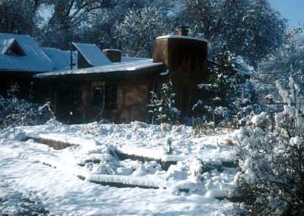
Interior
The wetland continues to adequately treat the wastewater even in winter although the area required for treatment is double of the summer requirement.
Hopefully this case study project has raised some questions in your mind. How deep is the subsurface wetland? Which contaminants are treated and to what level? How is the system sized and how does one know how much evaporation there will be? Does it smell bad? Which plants can grow in these conditions?
We will answer all of these questions and more in the next presentation.
Study Questions
List the three types of constructed wetlands used for wastewater treatment.
How many square feet of HSSF wetland area per person served is required to meet EPA secondary treatment standards in summer and winter?
Provide the HSSF wetland specification for the following items
Inlet and outlet trench width and gravel size
Main bed depth and gravel size
Percent slope on the top and bottom of the bed
Residency time required to meet secondary water quality standards
HSSF wetlands are ineffective at converting ______________ to nitrate.
True/False. Phosphorus, ammonia and nitrate are not regulated for secondary treatment in the US except under special circumstances.
True/False. In Ondrejov, Czech Republic the HSSF wetland removed BOD o and TSS to less than 20 mg/L
What accounted for the better reduction of ammonia (85.1%) in the HSSF wetlands at Little Stretton?
Specify the materials used in the three layers of the University of New Hampshire gravel wetland.
Wetland soil
Gravel transition
Main gravel bed
True/False. The performance of the University of New Hampshire gravel wetland demonstrated at least 95% removal of dissolved inorganic nitrogen, total suspended solids, zinc, and total petroleum hydrocarbons and diesel.
True/False. Although the porous paving and gravel wetland at the Greenland Meadows shopping center performed better it cost lightly more than a conventional system of stormwater sewers and detention ponds.
In the residential wastewater treatment project designed by Paul Lusk, how was the basin of the wetland constructed?
In the Lusk constructed wetland how much water is discharged into the the local stream?
The Lusk constructed wetland is in a climate that receives snow. How much additional area is required for winter treatment?
Name one aquatic plant that is commonly planted in ornamental wetlands.
References
Thomas Ballestero, Robert Roseen, James Houle Alison Watts, Tim Puls. Subsurface Gravel Wetlands for the Treatment of Stormwater. Presented at the NJASLA 2012 Annual Meeting and Expo in Atlantic City, NJ, January 29-31, 2012.
J. Vymazal, “Constructed Wetlands for Wastewater Treatment,” Water, vol. 2, no. 3, pp. 530–549, 2010.