Vertical Flow Constructed Wetlands
Horizontal Subsurface Flow Wetland (left), Vertical Flow Subsurface Wetland (right)
A – Inlet from septic tank; B – Horizontal flow through medium to fine gravel; C – Recirculation of 50% of the flow from VSF to HSF wetland for de-nitrification; D – Collection zone, coarse gravel; E – Water level control; F – Intermittent dosing of VSF; G – Water drains vertically through gravel to bottom drain; H – Outflow to free water wetland; I – Dense planting. Austin, 2009
The vertical flow subsurface flow wetland is similar to the horizontal flow version but uses a different biological and chemical system since it is an aerobic (oxygen rich) environment instead of the oxygen depleted environment typical of a HSSF wetland. See the image above and note that from the surface the wetlands look alike. The vertical subsurface flow (VSSF) wetland is shown on the right side of the section. Study the components and note the recirculation piping and rate.
Plan Elements
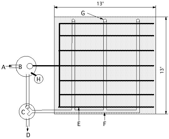
Vertical Subsurface Flow Wetland, Plan. A – Inflow from residence. B – Septic tank C – Recycling tank with V-notch weirs. D - Effluent. E- 1 ½” perforated PVC distribution piping, capped, 3’ spacing. F – 4” perforated PVC drainage piping, 3’ spacing. G – Aeration pipes connected to bottom drain H - Aluminum polychloride dosing chamber with air-lift pump in septic tank, for phosphorus removal. Source: Adapted from Brix, 2005
The vertical subsurface flow (VSSF) wetland receives periodic doses of pretreated water over its entire top surface but beneath a layer of mulch or gravel so that no water is ever exposed to human contact. Then the water flows down through a coarse sand bed and out of the wetland through a bottom drain. The image above shows a standard design adopted by the government in Denmark. Up to 13 residences can be connected to a larger version of the wetland without special permits or engineering calculations.
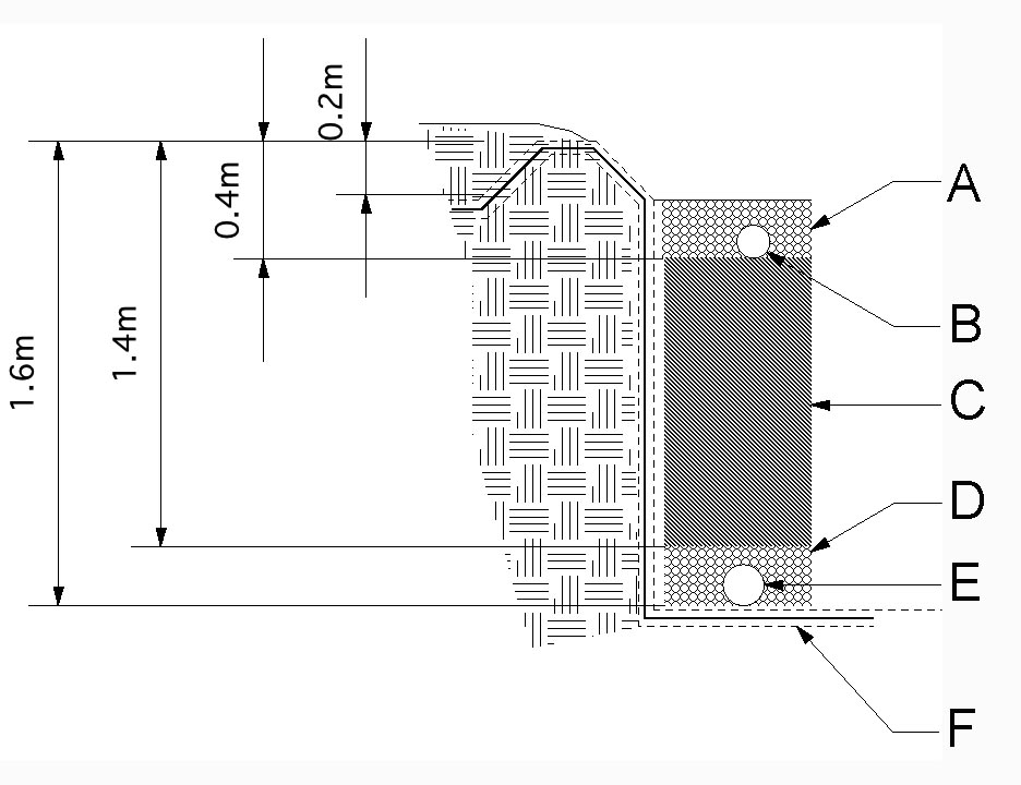
VSSF Wetland - section. A - Wood chips. B – 1 ½” PVC distribution pipes, space 3’ max. C - Uncompacted filter sand, .125-4 mm with clay and silt <.5%. D- ½ “ drain rock. F - .5 mm waterproof membrane between two geotextile layers. E – 4” perforated PVC, space 3’ max. At one end connect to aeration pipes that extend above surface. Source: Adapted from Brix, 2005.Photo: drawing adapted from Brix, 2005.
Air replaces water in the sand pore spaces after the water flows through. This system creates an oxygen rich environment where bacteria reduce BOD, TSS and convert ammonia to nitrates. VSSF wetlands require only 21.5 ft2 (2 m2) per person but they sometimes require energy input for pumps, and more regular attention from an operator (Tuncsiper, 2009). Vertical flow wetlands are often designed as a sequence of two cells to extend their performance to tertiary levels.
Construction Sequence
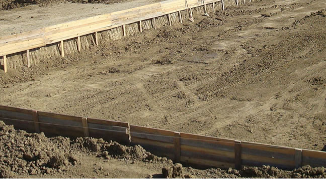
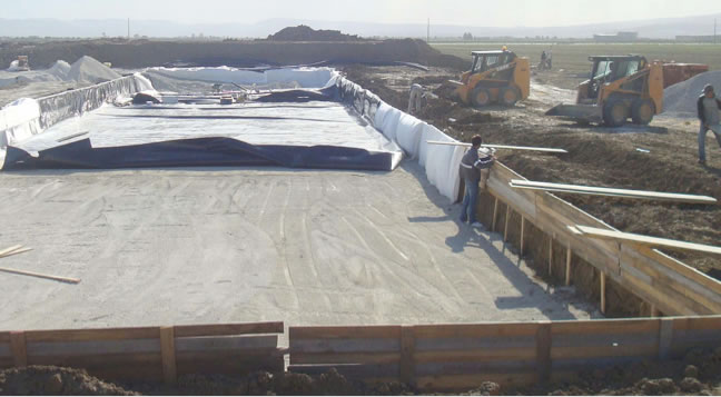
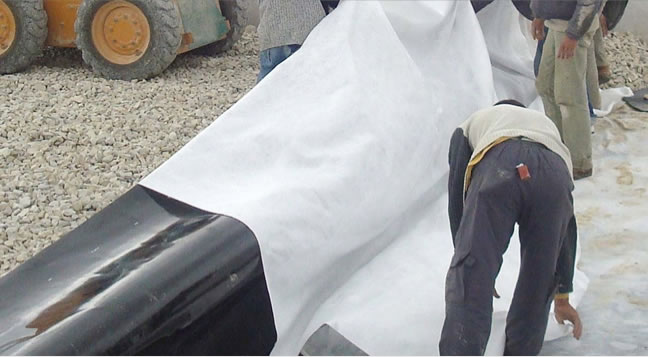
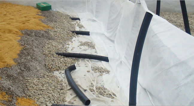
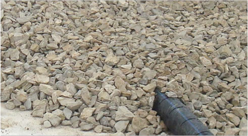
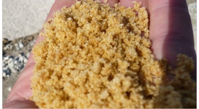
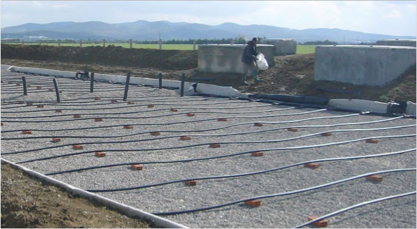
Top row 1. Excavation and forming 2. Placing geotextile layer and waterproof membrane 3. Creating the divisions between the wetland cells 4. Placement of the drain pipes, drain rock and filter media 5. Drainage detail
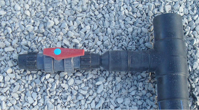
Bottom row 1. Coarse sand filter media 2. Distribution piping with siphon vaults in the background 3. Siphon tube 4. Valve to balance inflow rate 5. Planting (the last image is from a different project Photos : http://athene.geo.univie.ac.at/ except bottom row #5 which is from Blumberg Engineers
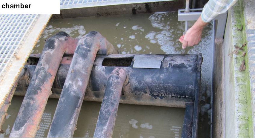
The sequence of images above show the construction steps for vertical subsurface flow wetlands. In particular notice the siphon vaults in bottom row #2. Theses allow the intermittent flooding of the VSSF wetland without the use of any pumps or power. Not shown in the sequence above is the pre-treatment septic tank.
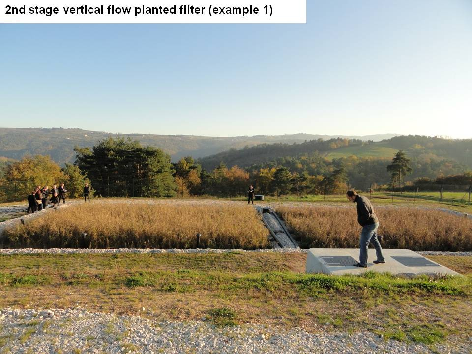
Two Stage Vertical Flow Constructed Wetland
![]()
Left: Stage Two of a VSF Wetland in France. Photo: Sustainable Sanitation, license CC-By-SA 2.0. Center: Two stage vertical flow wetland similar to the Austrian case study discussed below. Image: Austin.
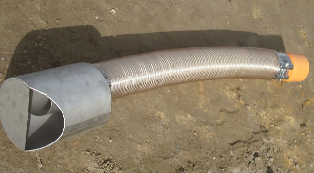
Right: Siphon. The barrel floats to the top of the tank then is stopped and fills with water. This causes the barrel to drop and open a valve that discharges all of the water in the tank into the wetland.
VSSF wetlands have been installed and monitored over long periods to document and refine the designs. An Austrian demonstration wetland featured two VSSF stages operated in series (above center). Each of the wetlands was 108 ft2 (10 m2) and was planted with Common Reed (Phragmites australis).
The first cell of the two-stage system included a 20” (50 cm) deep bed filled with sand ranging from 0.08” - .12” (2 - 3.2 mm) and an a 24" deep impounded basin of water below the filtration bed. The second VSSF stage included a 0.002” - 0.016” (0.06 - 4 mm) sand layer above a conventional coarse aggregate (3/4") drainage layer. Sewage, pretreated in a septic tank, flooded the top of the wetland to a depth of .64” (16.2 mm) every three hours.
The demonstration wetland was operated and monitored from September 2005 to May 2007. Inlet BOD was high at 340 mg/L while the effluent was 4 mg/L in summer and 12 mg/L in winter. The removal efficiency for BOD was 98.7% (Langergraber, 2009). Both were well below the US EPA target of 30 mg/L.
| Effluent | ||||
Contaminant |
Influent |
Summer |
Winter |
% Removal |
BOD |
340 |
4 |
12 |
98 |
Ammonia |
53.4-59.3 |
.29 |
17.5 |
64-99.5 |
Nitrate |
.3-.37 |
30.9 |
21.1 |
|
Total Nitrogen |
|
|
|
53.2 |
Units = mg/L
Ammonia and Nitrate Removal
In the Austrian demonstration wetland, the average ammonia concentrations of the influent were high at 59.3 mg/L in summer and 53.4 mg/L in winter. The ammonia effluent average was 0.29 mg/L in summer (a 99.5% reduction) and 17.5 mg/L in winter (a 64% reduction). This two-stage VSF wetland removed 46% more of the ammonia concentration than a single cell VSF wetland with no impoundment of water below the filter bed (Langergraber, 2009). The US does not regulate ammonia discharge but aquatic organisms are sensitive to constant levels in excess of 1.8 mg/L at Ph-8 and 77º F (25º C) (EPA, 2009).
The concentration of nitrates entering the two-stage wetland averaged .37 mg/L in summer and .30 mg/L in winter. Nitrates in the effluent were 30.9 mg/L in summer and 21.1 mg/L in winter. This large increase indicates complete conversion of ammonia (Langergraber, 2009).
Elimination of total nitrogen was 53.2% in summer and 37.1% in winter. This high performance in the removal of nitrogen is attributed to the nitrification of about 80% of the ammonia in the first stage wetland with the water impoundment but with enough carbon remaining to allow conversion of some of the nitrate to nitrogen gas in the impoundment, although not all of the nitrate was removed. The elimination of total nitrogen over the entire study was 2.7 g/m2 or 986 g/m2 per year (Langergraber, 2009). This nitrogen removal represents a 30% increase over the average VSSF wetland and even better compared to FWS and HSSF wetlands (Vymazal, 2007). The second stage of the two-part system is required to provide full nitrification of ammonia and elimination of the remaining organic matter. This two-stage wetland removed 64% more total nitrogen than a single cell VSSF wetland (Langergraber, 2009). This improvement is attributed to the increased nitrification and de-nitrification.
Removal of Pathogenic Bacteria

E. coil bacteria colonies. . Photo: Madprime cc-by-sa 3.0
In the Austrian demonstration wetland, the log influent concentration of heterotrophic bacteria was 6.32 with an effluent concentration of 3.45 representing a log removal of 2.87. For E. coli the influent concentration was 6.18 while the effluent concentration was 3.2, representing a log removal of 3.31. For total coliform bacteria, average concentration of the influent was 6.56 while the effluent concentration was 3.49 representing a log removal of 3.42. For Enterococci (a genius of pathogenic bacteria) the influent concentration was 5.94 while the effluent concentration was 2.76 representing a log removal of 3.36 (Langergraber, 2009). In summary, numbers of pathogenic bacteria were reduced about 99.9%. However, the remaining number of E. coli, for example, is 1,585 cfu/100 mL, which is still much higher than the 126 cfu/100 mL recommendation of the US EPA for primary contact. Additional treatment in another wetland stage or ultra violet light disinfection would be required before this effluent could be used for intensive recreation.
This two-stage VSF constructed wetland with impoundment but without recirculation of water performed consistently better in removal of nutrients than a single stage system without impoundment. The single stage and two-stage constructed wetlands were similarly effective in the removal of microbes although the hydraulic loading of the two-stage system was twice as high as that of the one stage system (Langergraber, 2009).
Performance of VSSF Compared to Other Constructed Wetland Types
![]()
![]()
The tables above compare the performance of the VSSF wetland with the other types. Left: Performance for BOD and TSS. Right: Performance for nitrogen and phosphorus.
Legend: Treatment efficiency (Eff, in %) of various types of Inflow (In) and outflow (Out) concentrations in mg/L. HLR = hydraulic loading rate (cm/d). N = number of constructed wetlands. Source: 2010.
You can see that the performance of the VSSF wetlands have better performance for BOD and TSS than the other wetland types. This is also true for ammonia, but the removal to total nitrogen is comparable because nitrate removal is poor.
Widespread Application
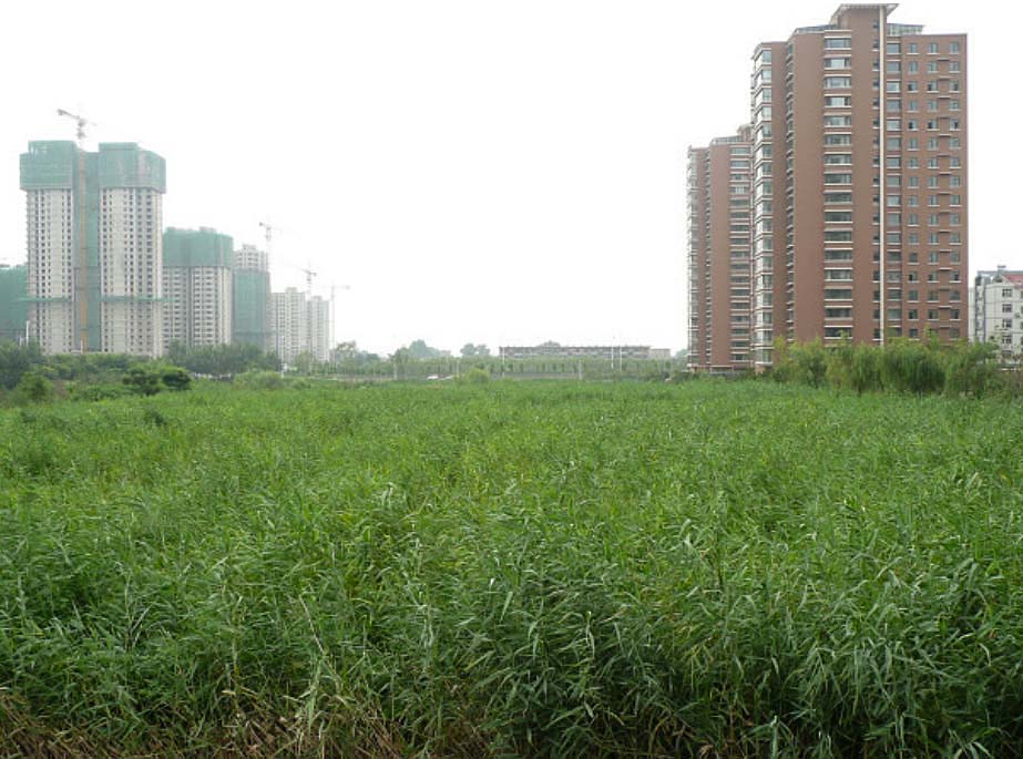
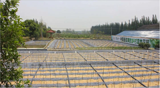
VSSF wetland treating wastewater for 6,000 people in China. Photo: Blumberg Engineering
Austria, France and Denmark all have ordinances defining the size, construction materials and performance standards for subsurface flow wastewater treatment (Cooper, 2009, Brix, 2005). Most of these are horizontal subsurface flow wetlands but vertical subsurface flow wetlands are becoming more popular because they require less land and perform well in removal of ammonium in addition to BOD and TSS. The two types of subsurface wetlands can be used in sequence.
The HSSF and VSSF wetlands are presented as panels of dense vegetation that could be treated aesthetically to contribute to the public landscape. The potential for dispersed constructed wetlands that treat wastewater, rather than the current centralized, industrial approach, has great promise. Placing these constructed wetlands at institutions, like schools, or within new subdivisions or adjacent to multifamily buildings would contribute to the green infrastructure networks promoted by landscape architects. As the data presented above on the performance of each constructed wetland type indicates, none by itself is capable of fully treating wastewater for all water quality parameters. Combinations of the wetland types are more effective for advanced wastewater treatment.
Hybrid Wetlands
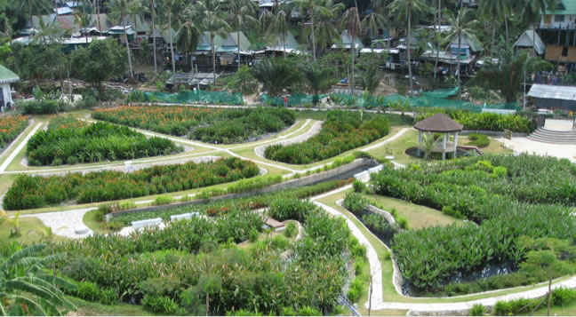
Hybrid wetland on Koh Phi Phi island near Thailand. Photo: Hans Brix.
The image above shows a wastewater treatment wetland that is also a city park. This is a hybrid system, since it includes VSSF, HSSF and Free Water Surface wetlands. The VSSF wetlands are the initial treatment step. They are the wedge shaped panels in the upper left of the image.
Study Questions
Does the vertical subsurface flow wetland receive continuous or intermittent water inflow?
In the sections of the horizontal and vertical subsurface flow wetland, recirculation is required for optimal performance for the removal of nitrogen. What is the recommended recirculation rate?
Annotate the plan and section of the VSSF wetland shown below.
For treatment of domestic wastewater, VSSF wetlands require only _________ square feet per person served.
In Austrian two-stage VSSF demonstration wetland how often and to what depth was the wetland surface flooded?
In Austrian two-stage VSSF demonstration wetland what was the summer and winter ammonia removal percentage?
True/False. In Austrian two-stage VSSF demonstration wetland, the amount of nitrate increased since VSSF wetlands are aerobic.
True/False. In Austrian two-stage VSSF demonstration wetland, pathogenic bacteria were reduced about 99.9% and met the US EPA standard of 126 cfu/100 mL recommendation for primary contact.
References
H. Brix and C. A. Arias, “The use of vertical flow constructed wetlands for on-site treatment of domestic wastewater: New Danish guidelines,” Ecol. Eng., vol. 25, no. 5, pp. 491–500, 2005.
K. L. Guenter Langergraber and R. H. Roland Rohrhofer, “High-rate nitrogen removal in a two-stage subsurface vertical flow constructed wetland,” Desalination, vol. 246, pp. 55–68, 2009.
J. Vymazal, “Removal of Nutrients in Various Types of Constructed Wetlands,” Sci. Total Environ., vol. 380, pp. 48–65, 2007.